Optical space positioning system and space positioning method thereof

A spatial positioning and optical technology, which is applied in the field of optical engineering and sensing, can solve the problems of small field of view, cumbersomeness, and small detection range of the photoelectric position detection, and achieves diversification of detection range, reduction of the number of lenses, and weight reduction. Effect

Active Publication Date: 2021-01-26
SHANGHAI UNIV
View PDF5 Cites 0 Cited by
  • Summary
  • Abstract
  • Description
  • Claims
  • Application Information

AI Technical Summary

Problems solved by technology

[0005] The object of the present invention is to solve the problem that the detection range of the existing photoelectric position detector is small and bulky, to provide an optical space positioning system and a space positio

Method used


Image

  • Optical space positioning system and space positioning method thereof
  • Optical space positioning system and space positioning method thereof
  • Optical space positioning system and space positioning method thereof

Examples


Embodiment 1

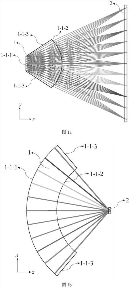
[0031] see figure 1 , an optical space positioning system, comprising a toroidal lens 1 and a linear array photosensitive element 2, the toroidal lens 1 and the linear array photosensitive element 2 constitute a detection unit, and at least three detection units are distributed in different positions in space , and the direction of the line photosensitive element 2 in at least one unit is not parallel to the direction of the line photosensitive element 2 in other units, forming a complete spatial positioning system.

[0032] The optical spatial positioning system of this embodiment can not only detect a small range of angles, but also be suitable for positioning operations within a detection range of a wide range of angles. Therefore, the optical spatial positioning system of this embodiment has wider adaptability in detection range angles. At the same time, the optical spatial positioning system of this embodiment can especially realize high-precision positioning within a la...

Embodiment 2

[0034] This embodiment is basically the same as Embodiment 1, and the special features are as follows:

[0035] In this embodiment, the toroidal lens has two optical surfaces, each of which takes the center of the line array photosensitive element 2 as the center of rotation, and the combination of the two optical surfaces can focus the light beam onto the line array photosensitive element 2 , the linear photosensitive element 2 is composed of micron-scale photosensitive pixels arranged in a straight line.

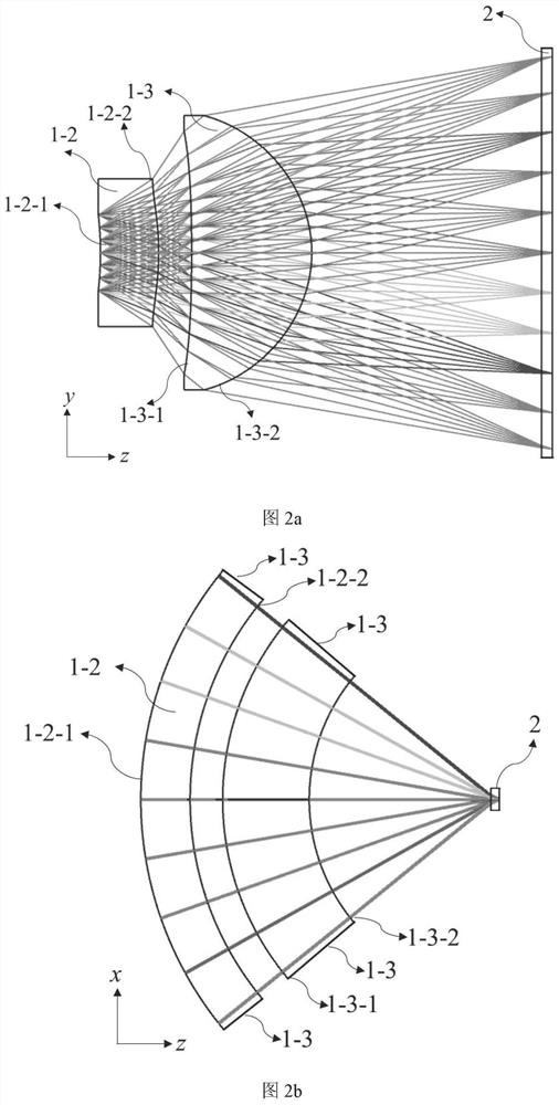
[0036] In this embodiment, the toroidal lens 1 is composed of one lens, or is composed of two toroidal lenses 1-2 and 1-3, or is composed of more than two toroidal lenses, each of which All the toroids take the center of the line photosensitive element 2 as the center of rotation.

[0037] In this embodiment, the combination of the optical surfaces of the toroidal lens 1 can focus light beams onto the linear photosensitive element 2 .

[0038] The optical space positioni...

Embodiment 3

[0041] This embodiment is basically the same as the above-mentioned embodiment, and the special features are as follows:

[0042]A space positioning method using the above-mentioned optical space positioning system, the operation steps are as follows:

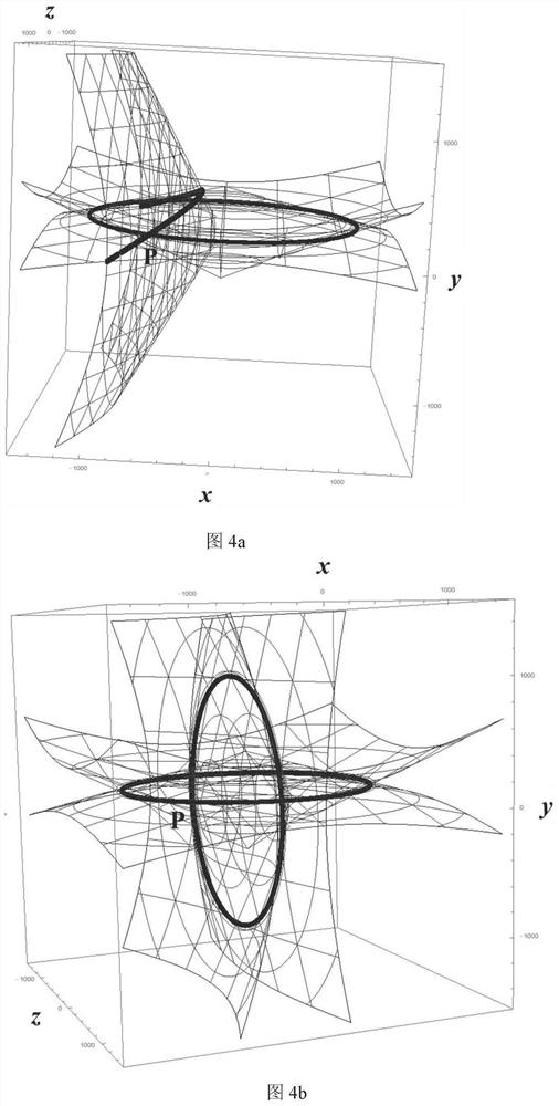
[0043] Step 1, the toroidal lens 1 is equivalent to a circular arc, and the position of the pixel point illuminated by the light of the linear array photosensitive element 2 is obtained, and the point and the circular arc form a conical surface;

[0044] Step 2. At least three cone surfaces intersect at one point in space; the position of the point is calculated by solving the cone surface equations, which is the position of the detected point.

[0045] This embodiment can realize the high-precision detection function of a wide range of spatial positions, and the cost is low.


PUM


Abstract

The invention discloses an optical space positioning system and a space positioning method thereof. The system consists of at least three groups of detection units consisting of tire tread lenses andlinear array photosensitive elements. The tire tread lens converges light emitted by the point light source in the space into a linear shape and is received by the linear array photosensitive element,and the linear array photosensitive element is located in the surrounding center of the tire tread lens. The detection units composed of at least three tire tread lenses and linear array photosensitive elements are arranged in a non-parallel mode in the space, and the position of the spatial point light source relative to the detector is calculated by obtaining intersection point position coordinates of light emitted by the point light source in the space and the linear array photosensitive elements in each detection unit. According to the invention, a function of high-precision detection ofa large-range spatial position can be realized, and the cost is low. The invention belongs to the field of space positioning.

Description

technical field [0001] The invention relates to a new configuration space positioning system and a space positioning method thereof, belonging to the fields of optical engineering and sensing. Background technique [0002] Positioning technology is mainly divided into indoor and outdoor in terms of application scenarios. At present, outdoor positioning mainly relies on satellite technologies such as GPS or Beidou. The positioning accuracy error of this technology is generally above 3m. Although it can meet most needs, it needs to rely on other technologies for positioning with higher precision requirements. For indoor positioning, since there is generally no GPS signal, technologies such as WIFI, Bluetooth, Zigbee, and UWB are mainly used, but the positioning accuracy is difficult to reach the millimeter level. [0003] The ultra-high-precision positioning technology mainly adopts the photoelectric detection method, that is, the detection unit is composed of at least three ...

Claims


Application Information

Patent Timeline
IPC IPC(8): G01S5/16
CPCG01S5/16
Inventor 杨建明屠晓伟杨庆华
Owner SHANGHAI UNIV
Why Eureka
Try Eureka