Facial mask forming machine

A molding machine and mask technology, which is applied in mixers, mixer accessories, mixers with rotating mixing devices, etc., to prevent the accumulation of a large number of raw materials and ensure the molding thickness.

Inactive Publication Date: 2021-01-29
田忠泉
View PDF1 Cites 5 Cited by
  • Summary
  • Abstract
  • Description
  • Claims
  • Application Information

AI Technical Summary

Problems solved by technology

The shortcoming of this invention is that can't carry out the mask forming production rapidly

Method used


Image

  • Facial mask forming machine
  • Facial mask forming machine
  • Facial mask forming machine

Examples


specific Embodiment approach 1

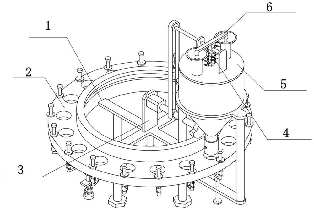
[0028] Combine below Figure 1-7 Describe this embodiment, a mask forming machine, including a support blanking assembly 1, a forming assembly 2, a drive assembly 3, a multifunctional assembly 4, a transmission assembly 5 and a feed switch assembly 6, the forming assembly 2 is rotatably connected to the support On the blanking assembly 1, the driving assembly 3 is fixedly connected to the supporting blanking assembly 1, the driving assembly 3 is fixedly connected to the forming assembly 2, the multifunctional assembly 4 is connected to the supporting blanking assembly 1, and the transmission assembly 5 is fixedly connected to the supporting On the blanking assembly 1 , the multifunctional assembly 4 is connected to the transmission assembly 5 , and the feed switch assembly 6 is connected to the supporting blanking assembly 1 .

[0029] The forming component 2 can be driven to rotate by the driving component 3, and the rotation of the forming component 2 on the support blanking...

specific Embodiment approach 2

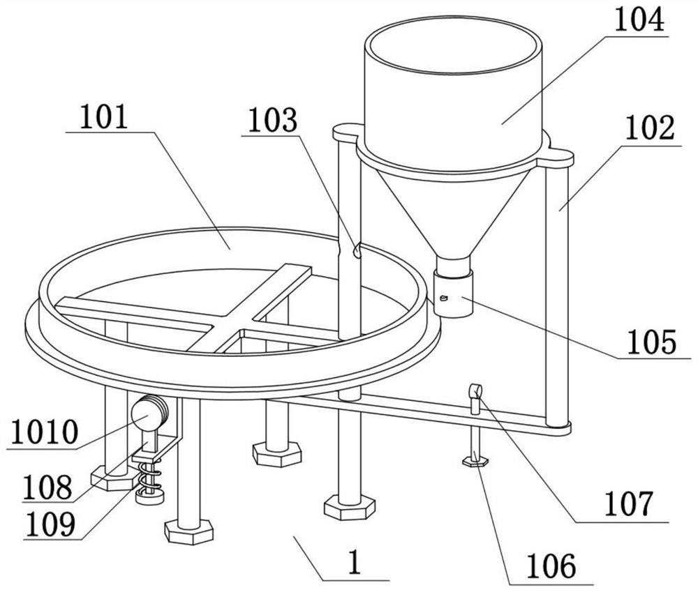
[0031] Combine below Figure 1-7To illustrate this embodiment, the supporting blanking assembly 1 includes a frame 101, a barrel frame 102, an auxiliary hole 103, a tapered barrel 104, an adjusting plunger tube 105, a thickness threaded rod 106, an adjusting wheel 107, a blanking telescopic rod 108, The blanking spring 109 and the blanking rotating wheel 1010, the barrel frame 102 are fixedly connected to the frame 101, the barrel frame 102 is provided with an auxiliary hole 103, the tapered barrel 104 is fixedly connected on the barrel frame 102, and the adjustment plunger pipe 105 is connected by thread At the lower end of the tapered barrel 104, the thickness threaded rod 106 is threadedly connected to the barrel frame 102, the adjustment wheel 107 is fixedly connected to the thickness threaded rod 106, the blanking telescopic rod 108 is slidably connected to the frame 101, and the blanking spring 109 is fixed Connected on the blanking telescopic rod 108 and the frame 101, ...

specific Embodiment approach 3

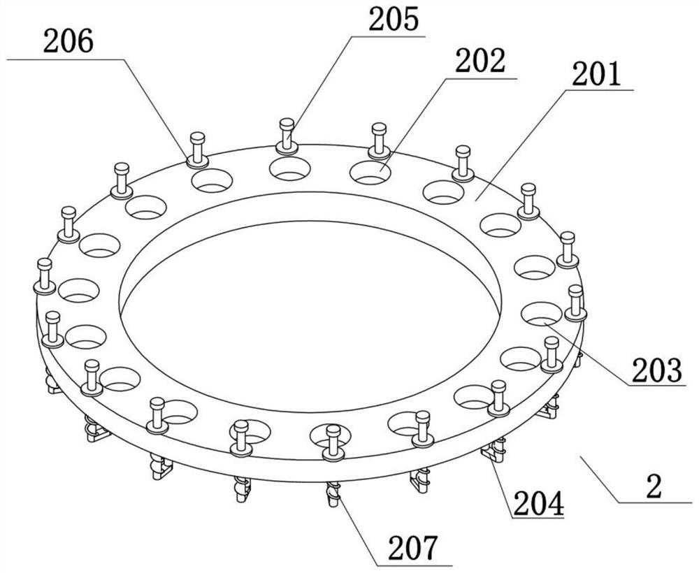
[0033] Combine below Figure 1-7 To illustrate this embodiment, the forming assembly 2 includes a forming turntable 201, a forming groove 202, a forming bottom plate 203, a bottom plate connecting frame 204, a guide slide bar 205, a limit ring 206 and a return spring 207. The forming turntable 201 is rotatably connected to the frame 101 Above, a plurality of forming grooves 202 are evenly distributed on the forming turntable 201, and forming bottom plates 203 are slidably connected in the plurality of forming grooves 202, and the lower ends of the plurality of forming bottom plates 203 are fixedly connected with a bottom plate connecting frame 204, and a plurality of bottom plate connecting frames 204 are fixedly connected with guide sliders 205, and a plurality of guide sliders 205 are slidably connected to the forming turntable 201, and a plurality of guide sliders 205 are connected with a limit ring 206 by threads, and a plurality of bottom plate connecting frames 204 and fo...


PUM


Abstract

The invention relates to the technical field of cosmetic forming equipment, in particular to a facial mask forming machine which has the advantage of being capable of rapidly conducting facial mask forming production. The facial mask forming machine comprises a supporting discharging assembly, a forming assembly, a driving assembly, a multifunctional assembly, a transmission assembly and a feedingswitch assembly. The forming assembly is rotationally connected with the supporting discharging assembly, the driving assembly is fixedly connected to the supporting discharging assembly, the drivingassembly is fixedly connected to the forming assembly, the multifunctional assembly is connected to the supporting discharging assembly, the transmission assembly is fixedly connected to the supporting discharging assembly, the multifunctional assembly is connected to the transmission assembly, and the feeding switch assembly is connected to the supporting discharging assembly.

Description

technical field [0001] The invention relates to the technical field of cosmetic molding equipment, more specifically a facial mask molding machine. Background technique [0002] The invention whose publication number is CN108082996A discloses a mask forming machine, which is provided with a mask cutting mechanism, which is used to cut out a mask on a roll material, and the output end of the mask cutting mechanism is docked-separated mechanism, and the separation mechanism is used to separate the roll material and the mask. In the present invention, a separation mechanism is provided after the mask cutting mechanism, which can effectively separate the mask from the roll material and facilitate subsequent processing; further, the separation mechanism is separated by an adsorption conveyor belt, and the separation process does not need to be stopped, thereby improving production efficiency. High, and the dust is sucked away by the vacuum suction device, and the production qual...

Claims


Application Information

Patent Timeline
Patent Type & Authority Applications(China)
IPC IPC(8): B07B1/34B07B1/42B01F7/24B01F15/00A61K8/02
CPCB07B1/34B07B1/42A61K8/0212B01F27/92B01F35/187
Inventor 田忠泉
Owner 田忠泉
Why Eureka
Try Eureka