Large-bore solar collector with improved stability

A solar collector and solar technology, applied in the field of solar collectors, can solve problems such as increased costs and even routine maintenance

Inactive Publication Date: 2003-10-01
ANUTECH
View PDF1 Cites 0 Cited by
  • Summary
  • Abstract
  • Description
  • Claims
  • Application Information

AI Technical Summary

Problems solved by technology

Collectors with usual apertures (e.g. circular, hexagonal, etc.) and using altitude/azimuth tracking, and at the same time their reflective structures balanced with respect to the horizontal axis to reduce drive effects, are alway

Method used


Image

  • Large-bore solar collector with improved stability
  • Large-bore solar collector with improved stability
  • Large-bore solar collector with improved stability

Examples


Embodiment Construction

[0039] When the invention is used with a solar reflector dish having a short focal length, the solar receiver is preferably mounted at or near the ground. Such receivers can be easily insulated. Material can be easily provided (or removed) to the receiver without the need for flexibility or swivel joints. The receiver can be of a more robust construction than if it were mounted at the focal point of a conventional large aperture reflector dish, on the end of a support beam.

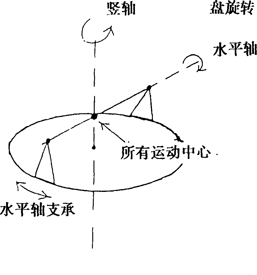
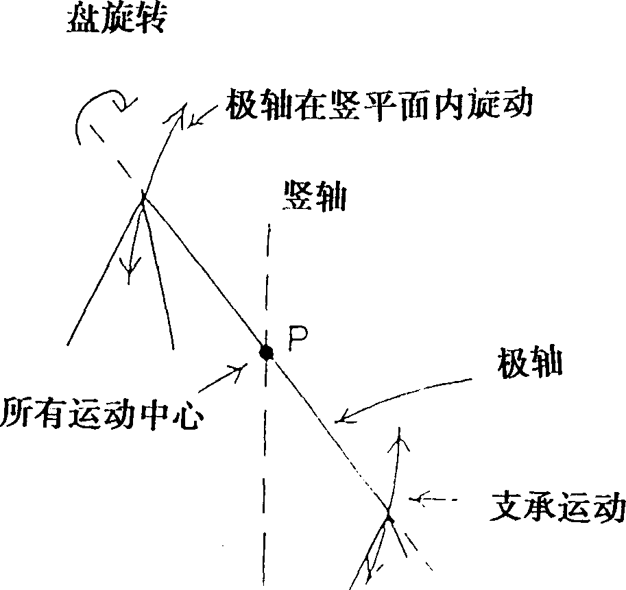
[0040] A receiver so mounted must be positioned so that the center of the receiver (or close to center) is at the center point of rotation of all axes of motion of the master platter. When the main disc is driven by altitude and azimuth, this point must be fixed and must be on the horizontal axis (such as the bisecting point of the axis between the axis coordinates) and also close to the ground on the vertical axis. this point in figure 1 The inner point P is not shown. There can be some latitude in w...


PUM


Abstract

A solar collector, with a large aperture, constituted as a main collector dish (MR), a secondary device (SR) and a receiver (P). Radiant energy such as solar energy is reflected from the main collector (MR) to an area on the secondary reflector (SR) and then focused on the receiver P. This allows the receiver P to be provided at a fixed location, such as on the ground or at a remote location, which allows easy access to the solar absorber and reduces maintenance costs, etc., eliminating the need for flexible or swivel joints, etc. The main collector (MR) can be constructed from multiple flat or curved reflector plates and reduce the cost of the collector MR. A modification such as removing the auxiliary reflector (SR) and placing the receiver P in its place.

Description

technical field [0001] This invention relates to solar collectors which use a large spherical or parabolic disk to concentrate the sun's rays into a single area within which the solar receivers are usually mounted. In particular, the present invention relates to an improved solar collector arrangement comprising a main collector and an associated small reflector for directing concentrated solar energy to a receiver area. The invention can be applied in the form of a receiver close to the main collector, or in the form of a heliostat in which multiple collectors each direct concentrated solar energy to a single, distant energy receiver. Background technique [0002] In solar applications, recent efforts have been directed towards the development of concentrated solar collectors with increased power, capacity and functionality. For example, a solar installation using a parabolic concave collector to supply heat to a turbogenerator is currently being used to provide 354 megaw...

Claims


Application Information

Patent Timeline
IPC IPC(8): F24J2/10F24J2/12F24J2/13F24J2/14F24J2/15F24J2/16F24J2/00F24S23/79H01L31/054
CPCY02E10/47Y02E10/52H01L31/0547F24S2020/16F24S23/79F24S30/452
Inventor 史蒂芬·卡尼夫
Owner ANUTECH
Why Eureka
Try Eureka