Slag-splashing converter protection gun position control method for steelmaking converter

A technology for protecting furnace with slag splashing and steelmaking converter, applied in the field of metallurgy, can solve problems such as unfavorable slag splashing protecting furnace, and achieve the effects of maintaining production, prolonging the life of furnace lining and uniform erosion rate

Pending Publication Date: 2021-01-29
PANGANG GRP PANZHIHUA STEEL & VANADIUM
View PDF8 Cites 0 Cited by
  • Summary
  • Abstract
  • Description
  • Claims
  • Application Information

AI Technical Summary

Problems solved by technology

[0006] The invention provides a method for controlling the position of the slag-splashing furnace protection gun in a steelmaking converter, which solves the problem that the existing slag-splashing gun position control method is not conducive to the slag-splashing furnace protection

Method used


Image

  • Slag-splashing converter protection gun position control method for steelmaking converter
  • Slag-splashing converter protection gun position control method for steelmaking converter
  • Slag-splashing converter protection gun position control method for steelmaking converter

Examples


Embodiment Construction

[0021] The present invention will be further described below in conjunction with embodiment.

[0022] The method for controlling the position of the slag-splashing protection gun of the steelmaking converter of the present invention comprises the following steps:

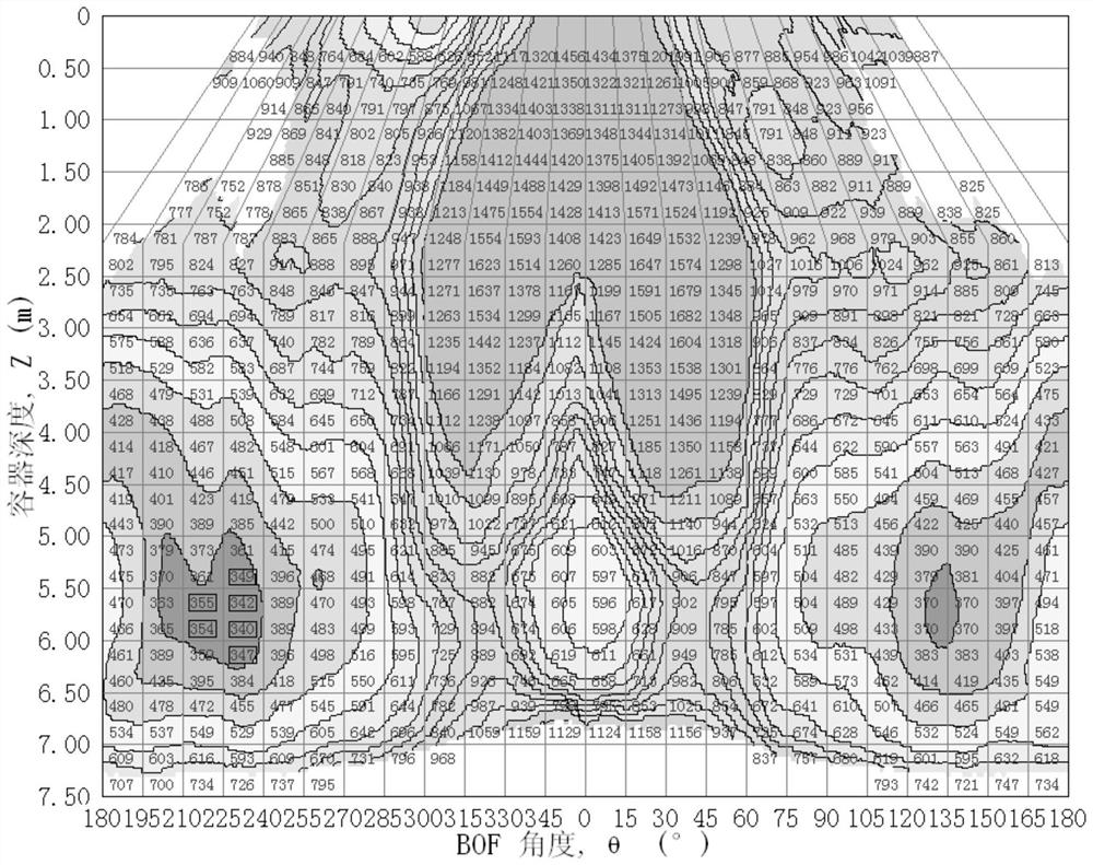
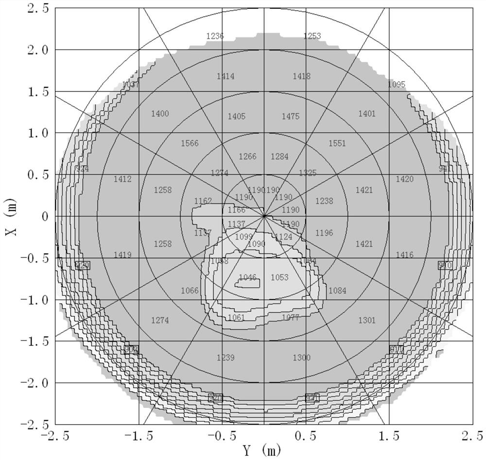
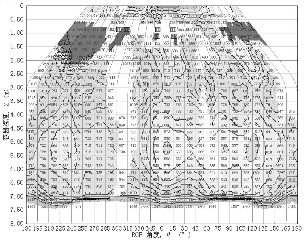
[0023] S1. Measure the erosion of each part of the furnace lining, obtain the position of the weak area of ​​the furnace lining, and determine the height of the area that needs slag splashing, that is, determine the slag splashing height H 高 , slag splash height H 高 including cap H 高上 and lower limit H 高下 . This step can be carried out at the end of tapping or when the furnace is shut down and waiting. Since the height of the slag splashing area is a range, the height of the slag splashing is also a range, and the range is recorded as the upper limit H 高上 and lower limit H 高下 .

[0024] For example, taking Panzhihua Iron and Steel No. 3 converter (furnace age 10240) as an example, the thickness of the convert...


PUM


Abstract

The invention discloses a slag-splashing gun position control method for a steelmaking converter, and relates to the field of metallurgy. The problem that an existing slag-splashing gun position control mode is not beneficial to slag-splashing converter protection is solved. According to the technical scheme, the slag-splashing gun position control method for the steelmaking converter comprises the following steps: firstly, measuring the erosion condition of each part of a converter lining to obtain the position of a weak region of the converter lining, and determining the height of a region to be subjected to slag splashing, namely determining the upper limit H height and the lower limit H height of the slag splashing height; calculating the upper limit H gun and the lower limit H gun ofthe slag splashing gun position according to a formula; and finally, after tapping of the converter is completed and the converter returns to the zero position, the gun positions are controlled according to the upper limit H gun and the lower limit H gun for slag-splashing converter protection. According to the method, the formula for calculating the slag-splashing height is provided, the slag-splashing gun position is calculated on the basis that the height of the region needing slag splashing is determined, slag-splashing converter protection is conducted accordingly, targeted slag-splashingcontrol over the weak area of the converter lining is achieved, the corrosion speed of the converter lining is uniform, and the service life of the converter lining is prolonged. The method is used for slag splashing of the steelmaking converter.

Description

technical field [0001] The invention relates to the field of metallurgy, in particular to a method for controlling the position of a slag-splashing protection gun in a steelmaking converter. Background technique [0002] During the charging and smelting process of the converter, various parts of the lining often have different erosion degrees due to the impact and erosion of scrap steel and molten iron and the erosion speed of slag and molten steel. At present, the furnace body is generally maintained by the slag splashing protection process in the industry, that is, the oxygen lance is used to spray high-pressure nitrogen gas into the converter molten pool. It is combined with the furnace lining to form a dense slag splash protection layer, thereby reducing the erosion of molten steel, slag and other factors during the blowing process, protecting the furnace lining and improving the life of the converter. [0003] With the general implementation of the slag splashing prote...

Claims


Application Information

Patent Timeline
IPC IPC(8): C21C5/44
CPCC21C5/443C21C2300/06Y02P10/25
Inventor 李盛姚恩学唐郁陈顺友郭勇熊超
Owner PANGANG GRP PANZHIHUA STEEL & VANADIUM
Why Eureka
Try Eureka