Lens and VCSEL device adopting lens

A lens and device technology, applied in the field of VCSEL devices, can solve problems such as low light extraction efficiency and low reliability of engineering beam expanders

Pending Publication Date: 2021-01-29
XI AN RAYSEES TECH CO LTD
View PDF6 Cites 0 Cited by
  • Summary
  • Abstract
  • Description
  • Claims
  • Application Information

AI Technical Summary

Problems solved by technology

[0003] The purpose of the embodiments of the present invention is to provide a lens, aiming to solve the pr...

Method used


Image

  • Lens and VCSEL device adopting lens
  • Lens and VCSEL device adopting lens
  • Lens and VCSEL device adopting lens

Examples


Embodiment Construction

[0022] In order to make the object, technical solution and advantages of the present invention clearer, the present invention will be further described in detail below in conjunction with the accompanying drawings and embodiments. It should be understood that the specific embodiments described here are only used to explain the present invention, not to limit the present invention.

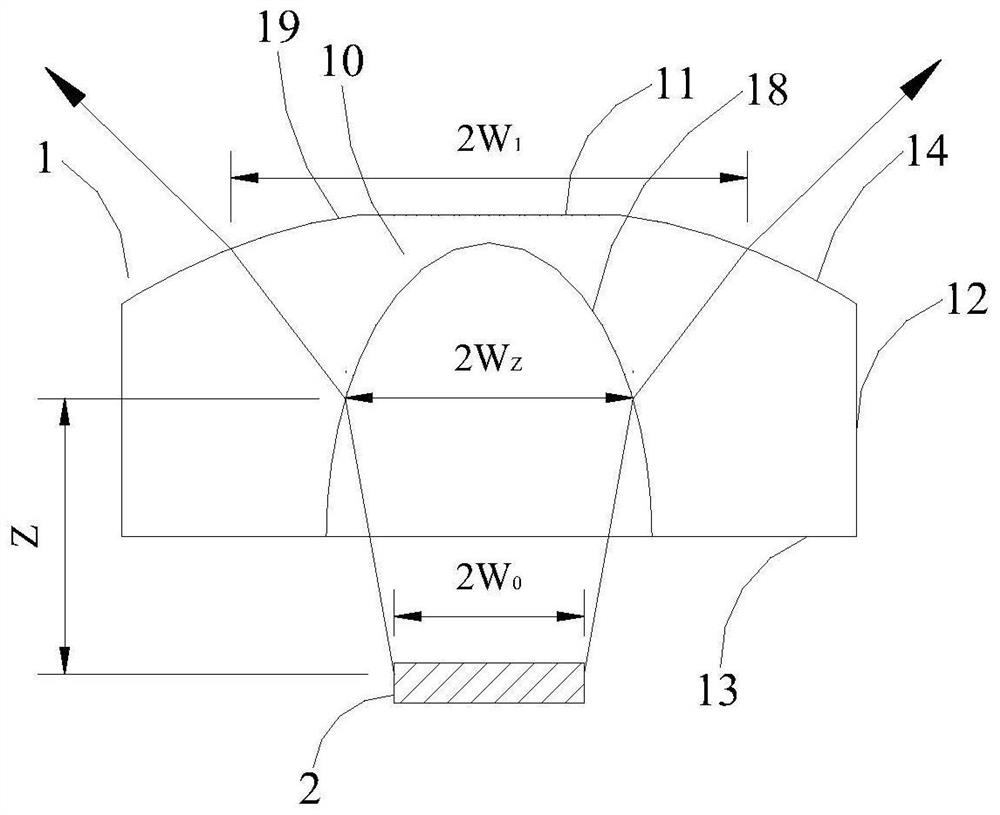
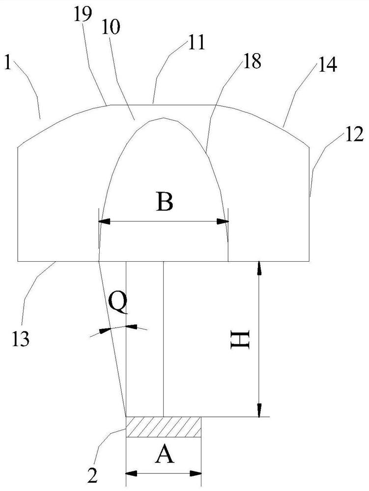
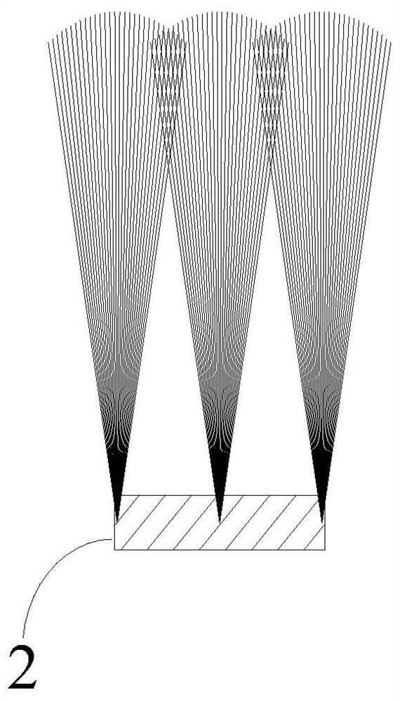
[0023] The lens provided in this embodiment does not have a polymer layer, and there is no human eye safety hazard caused by the high-temperature melting and falling off of the polymer layer or the failure caused by glue infiltration and pollutant filling, and the light extraction efficiency is high. The lens is a diverging lens with a functional area, which is used to expand the beam emitted by the VCSEL chip. The functional area includes a first optical interface at the bottom of the lens and a second optical interface at the top of the lens. The light beam emitted by the VCSEL chip is projected ...


PUM


Abstract

The invention is applicable to the technical field of photoelectricity, and provides a lens and a VCSEL device adopting the lens, and the lens is a diverging lens with a functional area and is used for expanding a light beam emitted by a VCSEL chip. The functional area comprises a first optical interface located at the bottom of the lens and a second optical interface located at the upper part ofthe lens, and a light beam emitted by the VCSEL chip is projected to the first optical interface of the functional area and is refracted by the first optical interface, so that the angle of the lightbeam is increased and is close to a preset light emitting angle; the light beam enters the lens from the first optical interface, exits from the second optical interface of the functional area, is refracted by the second optical interface, and is optimized and shaped to meet the preset light emitting angle and light spot requirements; wherein the preset light emitting angle ranges from 20-120 degrees. In this way, the light emitting angle of the VCSEL device adopting the lens is increased, the effective irradiation range is large, light is emitted in a homogenized mode, light spots emitted through the lens are uniform, and various application requirements can be met.

Description

technical field [0001] The invention belongs to the field of optoelectronic technology, in particular to a lens and a VCSEL device using the lens. Background technique [0002] At present, the VCSEL (Vertical Cavity Surface Emitting Laser, Vertical Cavity Surface Emitting Laser) chip uses an engineering beam expander 4 (Diffuser) for beam expansion. The engineering beam expander 4 is bonded to a polymer layer 42 on the surface of a flat glass 41, Use micro-refraction technology (including refraction and diffraction) to diffuse light, such as Figure 15 shown. Due to the high total reflection of the flat glass 41 and the microstructure of the polymer layer 42 will cause light loss, in actual tests, the optical loss of the VCSEL chip after beam expansion by the engineering beam expander is more than 10%, so the light extraction efficiency is relatively low . Moreover, the polymer layer is prone to high-temperature melting and falling off, or failure caused by glue infiltrati...

Claims


Application Information

Patent Timeline
IPC IPC(8): G02B3/00G02B27/09
CPCG02B3/00G02B27/0916G02B27/0966G02B27/0955G02B2003/0093
Inventor 黄伟曹宇星
Owner XI AN RAYSEES TECH CO LTD
Why Eureka
Try Eureka