
Automatic welding equipment

An automatic welding and equipment technology, applied in welding equipment, auxiliary welding equipment, welding/cutting auxiliary equipment, etc., can solve the problems of unqualified welding quality and difficulty in ensuring the stable state of two metal pipes, and achieve high welding reliability, The effect of high degree of automation and wide application range

Inactive Publication Date: 2021-02-02
深圳市励东科技发展有限公司
View PDF0 Cites 4 Cited by
  • Summary
  • Abstract
  • Description
  • Claims
  • Application Information

AI Technical Summary

Problems solved by technology

[0003] However, the welding method of metal pipes in the prior art is generally manual welding by workers. For manual welding, when workers work for a long time, their physical strength and attention will decline, and it is difficult to align the two metal pipes, and it is not easy to ensure that the two metal pipes are in the same position. Maintain a stable state during the welding process, resulting in unqualified welding quality

Method used


Image

  • Automatic welding equipment
  • Automatic welding equipment
  • Automatic welding equipment

Examples


Embodiment Construction

[0029] In order to make the object, technical solution and advantages of the present invention clearer, the present invention will be further described in detail below in combination with specific embodiments and with reference to the accompanying drawings. It should be understood that these descriptions are exemplary only, and are not intended to limit the scope of the present invention. Also, in the following description, descriptions of well-known structures and techniques are omitted to avoid unnecessarily obscuring the concept of the present invention.

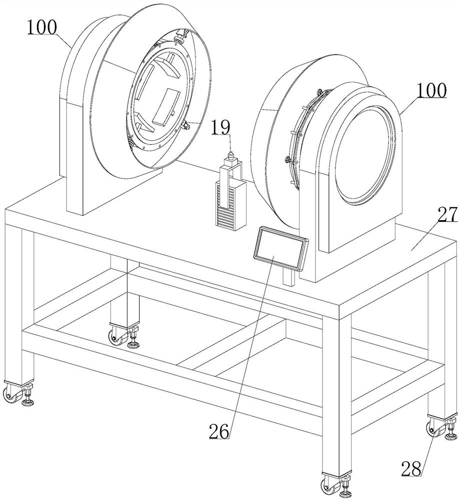
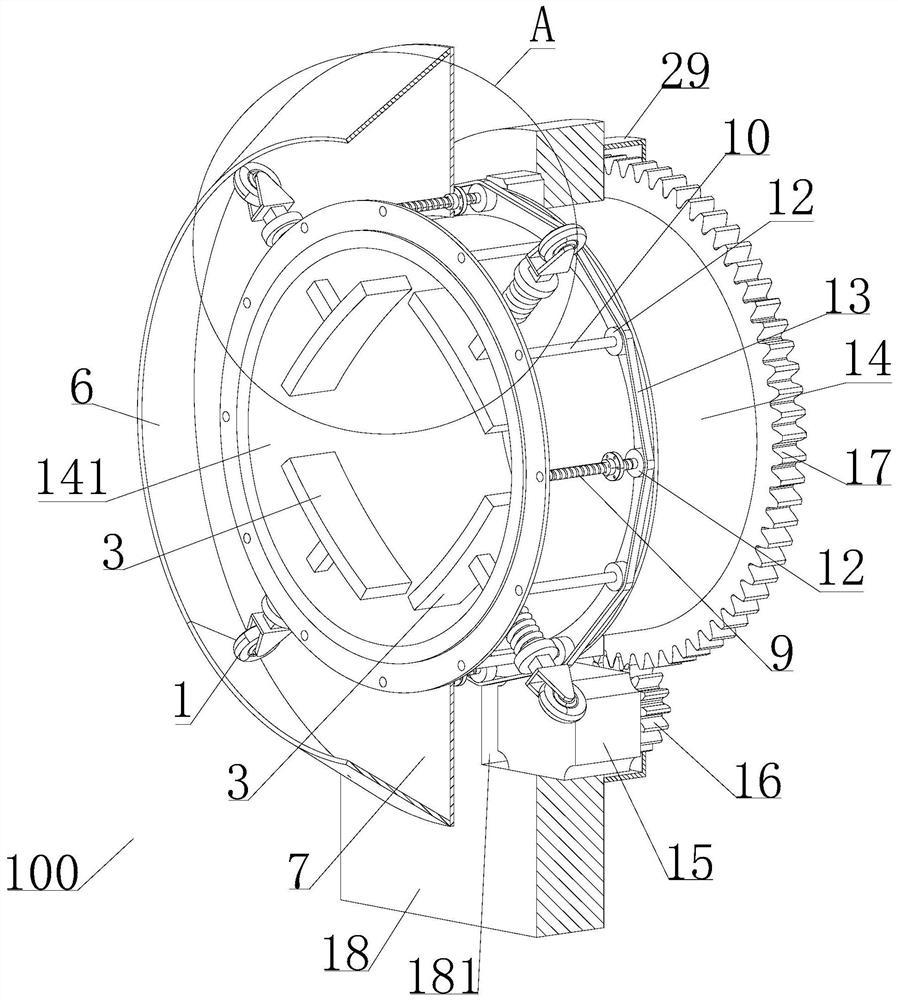
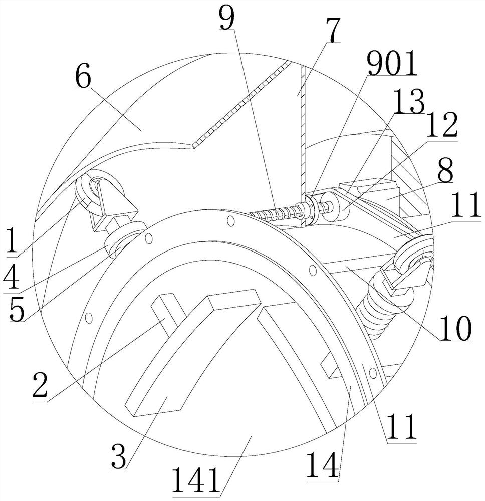
[0030] Such as Figure 1-4 As shown, a kind of automatic welding equipment proposed by the present invention includes a clamping and rotating mechanism 100, a welding head 19, a control panel 26 and a frame 27. It includes a clamping assembly, a push plate 6, a connecting plate 7, a rotating cylinder 14, a mounting table 18, a moving driving mechanism for driving the connecting plate 7 to move laterally, a rotating drivi...


PUM


Abstract

The invention discloses automatic welding equipment. The automatic welding equipment comprises clamp rotation mechanisms, a welding head, a control panel and a machine frame, wherein two groups of clamp rotation mechanisms are arranged abreast in the horizontal direction; each group of clamp rotation mechanisms comprises a clamping assembly, a push plate, a connecting plate, a rotary drum, a mounting table, a movable driving mechanism for driving the connecting plate to be moved in the horizontal direction and a rotation driving mechanism for driving the rotary drum to be rotated, wherein a lifting mechanism for driving the welding head to be lifted is arranged on the machine frame; a central shaft of the corresponding rotary drum is horizontally arranged; a clamp channel is coaxially arranged on the corresponding rotary drum; the rotary drum is rotatably arranged on the corresponding mounting table; the rotation driving mechanism is arranged on the corresponding mounting table; and the control panel is separately connected with the corresponding welding head, the corresponding movable driving mechanism, the corresponding rotation driving mechanism and the corresponding lifting mechanism. According to the automatic welding equipment disclosed by the invention, metal tube can be stably clamped and can be driven to be rotated, and in a rotation process of the metal tubes, the twometal tubes can be automatically welded through the welding head, and thus, the automation degree is high, the welding accuracy is high, and the welding quality is high.

Description

technical field [0001] The invention relates to the technical field of welding equipment, in particular to an automatic welding equipment. Background technique [0002] Metal pipe is a new structural material that has developed rapidly in water conservancy and hydropower projects recently, and has become an important material selected in the construction of high flow rate and high head water conservancy and hydropower water transmission structures. The pressure metal pipe is an important part of the metal pipeline, and has gradually attracted widespread attention from all walks of life. The pressure metal pipe is responsible for the connection between the turbine volute and the water inlet in water conservancy and hydropower projects, and can guide the water in the water inlet. , and make the water flow smoothly to the ball valve or the volute, and the water turbine rotates through the force of the water. The welding of metal pipes needs to meet the following basic procedur...

Claims


Application Information

Patent Timeline
Patent Type & Authority Applications(China)
IPC IPC(8): B23K37/00B23K37/04B23K37/047B23K101/06
CPCB23K37/00B23K37/0443B23K37/047B23K2101/06
Inventor 刘斌
Owner 深圳市励东科技发展有限公司
Learn More