Hole position detection device

A technology for detecting holes and fixing plates, which is applied in the direction of measuring devices, instruments, etc., can solve the problems of falling off of waste wafers, affecting the detection accuracy, not suitable for fast switching products and high efficiency requirements, etc., to facilitate adjustment, reduce consumables and repair and maintenance Frequency, the effect of improving the drop yield

Pending Publication Date: 2021-02-02
SHENZHEN JIXIANGYUN TECH CO LTD
View PDF0 Cites 0 Cited by
  • Summary
  • Abstract
  • Description
  • Claims
  • Application Information

AI Technical Summary

Problems solved by technology

The laser infrared detector is fixed on the processing head machine part through the L-shaped bracket, and is inclined downward at an angle of 30°-45°. The measurement purpose is achieved in real time through the principle of laser beam reflection. With the continuous change of customer product requirements, processing The shape of the hole is various. Through the multi-joint blowing nozzle, it will appear whether the processed waste wafers fall off naturally. There is no feedback information, and the equipment is executed according to the normal process, resulting in subsequent processes that will be damaged due to the waste wafers not falling off. Tool
The laser infrared detection beam has very high requirements on the cleanliness of the product, because dust will appear in the product during processing, which is easy to adhere to the laser infrared detector and affect the accuracy of detection; the requirements for installation and adjustment are relatively high, if the processing head machine adds The components need to be adjusted with the change of the focus, often needing 1-2 hours to adjust, and multiple calibrations can meet the detection requirements, which is not suitable for the high-efficiency requirements of fast switching products

Method used


Image

  • Hole position detection device
  • Hole position detection device

Examples


Embodiment Construction

[0022] The following will clearly and completely describe the technical solutions in the embodiments of the present invention with reference to the accompanying drawings in the embodiments of the present invention. Obviously, the described embodiments are only some, not all, embodiments of the present invention. Based on the embodiments of the present invention, all other embodiments obtained by persons of ordinary skill in the art without making creative efforts belong to the protection scope of the present invention.

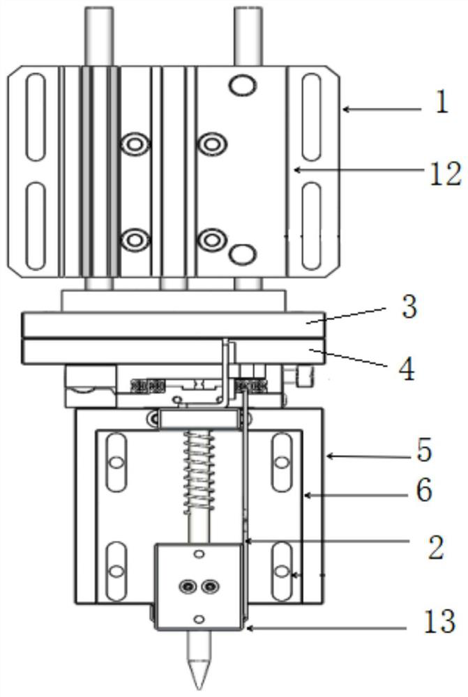
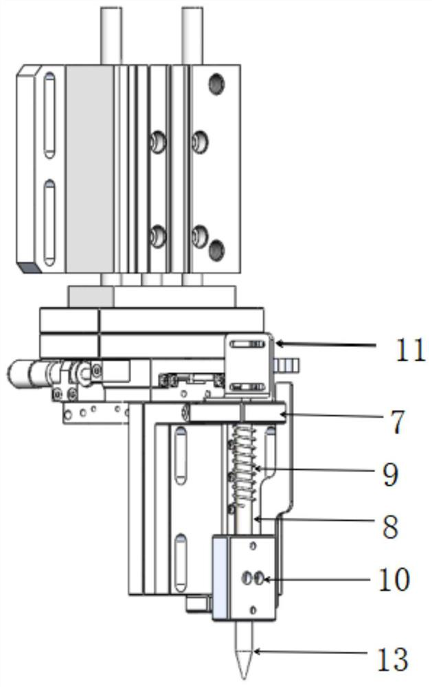
[0023] see Figure 1-2 , in an embodiment of the present invention, a device for detecting hole positions, including a cylinder fixing plate 1 and an induction plate 2;

[0024] The bottom of the cylinder fixed plate 1 is connected with a transfer upper fixed plate 3 in a lifting manner, and the bottom of the transferred upper fixed plate 3 is provided with a transfer lower fixed plate 4, and the bottom end of the transferred lower fixed plate 4 is fixedly con...


PUM


Abstract

The invention discloses a hole position detection device which comprises an air cylinder fixing plate and an induction piece. The lower portion of the air cylinder fixing plate is connected with an adapter upper end fixing plate in a lifting mode, an adapter lower end fixing plate is arranged below the adapter upper end fixing plate, the bottom end of the adapter lower end fixing plate is fixedlyconnected with a bottom plate, and the front side wall of the bottom plate is fixedly connected with a mounting fixing plate; a sliding block guide plate is fixedly connected to the mounting fixing plate, a guide column is vertically and fixedly connected to the lower surface of the sliding block guide plate, the guide column is sleeved with a spring, the guide column is movably sleeved with a balancing weight, and the induction piece is fixedly connected to the balancing weight. The machined waste wafer naturally falls off or not is detected through the air cylinder lifting assembly, the situation that the waste wafer flows into the subsequent procedure to damage the clamping jig is prevented, and consumables and the repair and maintenance frequency are reduced.

Description

technical field [0001] The invention relates to the technical field of glass, in particular to a hole position detection device. Background technique [0002] In the existing processing field of the glass industry, self-inspection is carried out after the product is processed and before it flows into the next process: blow air at the position of the processing hole through the round hole blowing nozzle, and output a signal to the electromagnetic through the control system after the product is in place and stops. Valve, solenoid valve to switch the air flow direction through the PU air pipe to the multi-joint blowing nozzle, and blow the processed product position briefly, so that the processed product position waste wafer will fall off the base material under the action of external force. The laser infrared detector is fixed on the processing head machine part through the L-shaped bracket, and is inclined downward at an angle of 30°-45°. The measurement purpose is achieved i...

Claims


Application Information

Patent Timeline
Patent Type & Authority Applications(China)
IPC IPC(8): G01B21/00
CPCG01B21/00
Inventor 陈燕张勇黄再福冯建华魏运起
Owner SHENZHEN JIXIANGYUN TECH CO LTD
Why Eureka
Try Eureka