Wind power boosting rotor ventilation and heat dissipation device

A technology for ventilation, heat dissipation and boosting, which is applied in cooling/ventilation devices, cooling/ventilation/heating renovation, pump devices, etc., and can solve the problems that affect the continuous operation of the rotor, affect the stability of the motor, and complex heat dissipation schemes.

Pending Publication Date: 2021-02-02
CSIC SHANGHAI MARINE ENERGY SAVING TECH DEV CO LTD
View PDF0 Cites 2 Cited by
  • Summary
  • Abstract
  • Description
  • Claims
  • Application Information

AI Technical Summary

Problems solved by technology

At the same time, the wind booster rotor is usually driven by a motor located inside the tower body. In order to maintain stability, the motor is generally placed at a higher position, and the overall space is relatively closed and limited, resulting in more heat often accumulated inside the tower body.
The high temperature will seriously affect the stability of the motor, and then affect the continuous operation of the rotor.
The rotor cooling devices in the prior art usually do not have ventilation holes, or cannot effectively perform ventilation and heat dissipation, or the heat dissipation scheme is too complicated, which increases the production cost

Method used


Image

  • Wind power boosting rotor ventilation and heat dissipation device
  • Wind power boosting rotor ventilation and heat dissipation device
  • Wind power boosting rotor ventilation and heat dissipation device

Examples


Embodiment 1

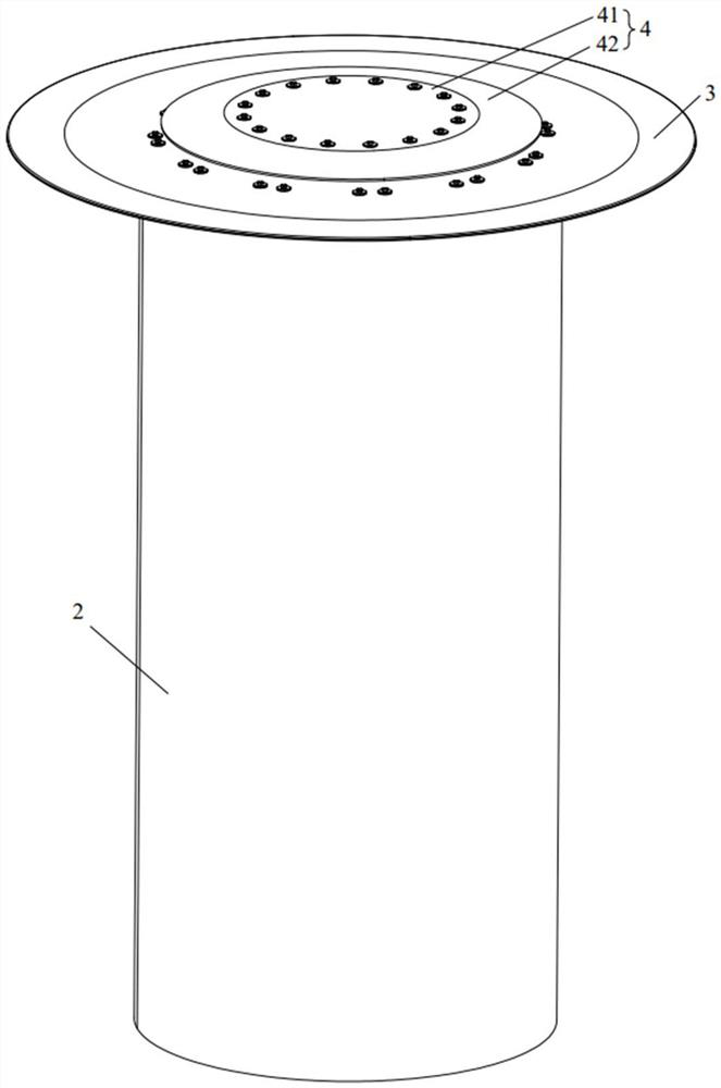
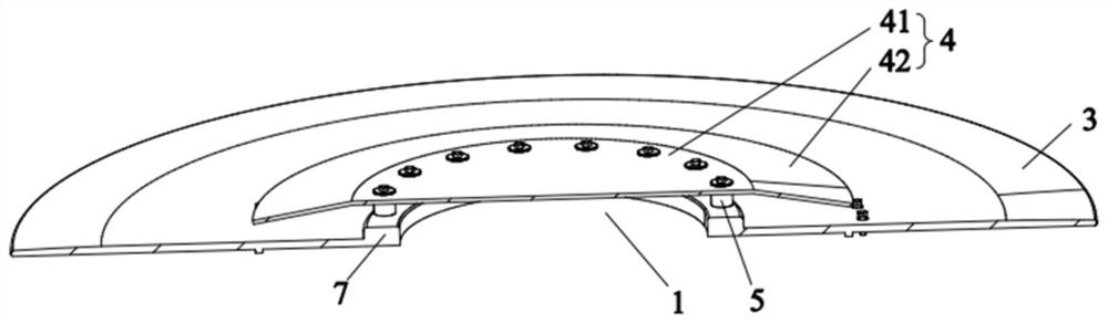
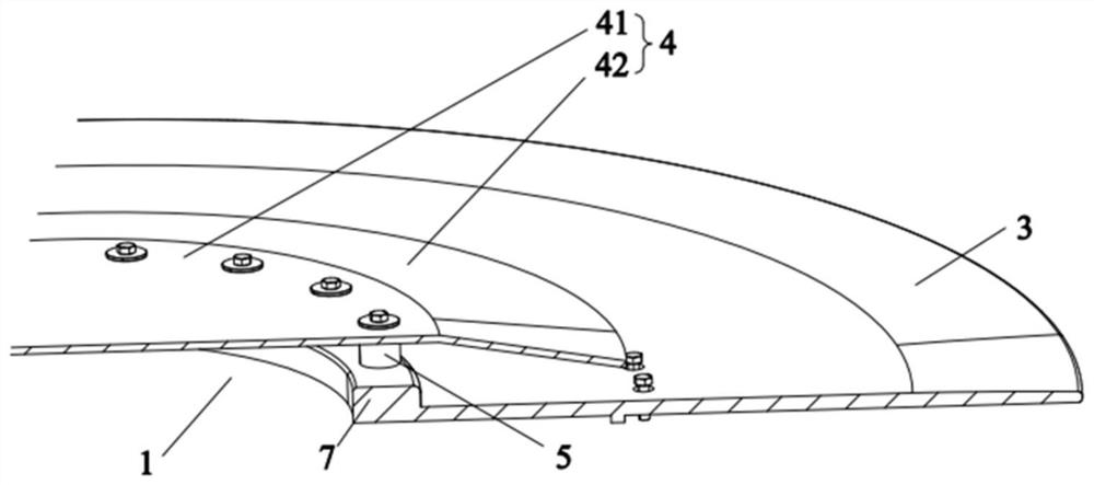
[0045] like figure 1 As shown, this embodiment provides a wind-assisted rotor ventilation and heat dissipation device, and the wind-assisted rotor ventilation and heat dissipation device includes a cylinder body 2 , a top cover 3 and a rain shield 4 . Specifically, such as figure 2 and image 3 As shown, the top cover 3 is covered and arranged on the top of the cylinder body 2 , and the manhole 1 is opened on the top cover 3 , and the manhole 1 communicates with the inner cavity of the cylinder body 2 . The rain shielding plate 4 is covered and arranged above the manhole 1, and the rain shielding plate 4 and the top cover 3 are spaced apart to form a heat dissipation gap communicated with the outside atmosphere. like Figure 4 As shown, in this embodiment, by setting the wind-assisted rotor ventilation and heat dissipation device, the heat inside the cylinder body 2 is dissipated to the outside atmosphere through the heat dissipation gap under the action of the exhaust fan...

Embodiment 2

[0053] This embodiment proposes a wind-assisted rotor ventilation and heat dissipation device, such as Figure 5 and Image 6 As shown, the difference between the wind-assisted rotor ventilation and heat dissipation device and the wind-assisted rotor ventilation and heat-radiation device in the first embodiment is only that the wind-assisted rotor ventilation and heat dissipation device in this embodiment has a reinforcing component 6 .

[0054] In order to further improve the structural strength of the flashing board 4 to cope with bad weather, the wind-assisted rotor ventilation and heat dissipation device in this embodiment may further include a reinforcement assembly 6 . like Figure 5 and Image 6 As shown, the reinforcement assembly 6 is provided on the lower surface of the flasher 4 between the flasher 4 and the top cover 3 . Specifically, as Figure 7 As shown, the reinforcing assembly 6 includes an inner lining plate 61 and a reinforcing rib 62, and the inner lini...


PUM


Abstract

The invention provides a wind power boosting rotor ventilation and heat dissipation device, and relates to the technical field of wind power boosting rotor heat dissipation. The wind power boosting rotor ventilation and heat dissipation device comprises a cylinder body, a top cover and a flashing board. Specifically, the top cover is arranged at the top of the cylinder body in a covering mode, anda manhole is formed in the top cover and communicated with an inner cavity of the cylinder body. The flashing board is arranged above the manhole in a covering mode, and the flashing board and the top cover are arranged in a spaced mode to form a heat dissipation gap communicated with the external atmosphere. Heat in the cylinder body is dissipated to the outside atmosphere through the heat dissipation gaps, and the flashing board can prevent rain and snow from entering the cylinder body in rainy and snowy days, so that a motor or other parts in the cylinder body are prevented from being damaged due to the influence of rain and snow. The wind power boosting rotor ventilation and heat dissipation device is simple in structure, good in heat dissipation and ventilation effect, low in manufacturing cost and suitable for practical application.

Description

technical field [0001] The invention relates to the technical field of wind-assisted rotor heat dissipation, in particular to a wind-assisted rotor ventilation and heat dissipation device. Background technique [0002] Wind-assisted rotors are usually large in size and need to maintain a high rotational speed to work continuously to provide continuous propulsion for ships to sail. The outer cylinder and the inner tower are generally connected by bearings, and continuous friction will generate a lot of heat. At the same time, the wind booster rotor is usually driven by a motor located inside the tower body. In order to maintain stability, the motor is generally placed at a higher position, and the overall space is relatively closed and limited, resulting in more heat often accumulated inside the tower body. The high temperature will seriously affect the stability of the motor, and then affect the continuous operation of the rotor. The rotor cooling device in the prior art u...

Claims


Application Information

Patent Timeline
Patent Type & Authority Applications(China)
IPC IPC(8): H05K7/20F04D25/12H02K5/04H02K5/10H02K9/04
CPCH05K7/20127F04D25/12H02K9/04H02K5/04H02K5/10Y02E10/72H02K9/02H02K5/207Y02E10/70
Inventor 郭峰山吴幼华朱玉柱黄振宇吴赞夏灏超陈少峰赵璐
Owner CSIC SHANGHAI MARINE ENERGY SAVING TECH DEV CO LTD
Why Eureka
Try Eureka