Supercharge Your Innovation With Domain-Expert AI Agents!

Vacuum low-temperature dehydration equipment with monitoring device

A monitoring device, vacuum and low temperature technology, applied in evaporator regulation/control, sub-atmospheric process, method of chemically changing substances by atmospheric pressure, etc. Processing status, etc.

Pending Publication Date: 2021-02-05
山东立威微波设备有限公司
View PDF0 Cites 0 Cited by
  • Summary
  • Abstract
  • Description
  • Claims
  • Application Information

AI Technical Summary

Problems solved by technology

Since most of the dehydration reactors in the prior art are in a closed state during the dehydration operation, the processing state of the food inside the reactor cannot be observed during the processing operation, which brings some inconvenience to the operation.

Method used


Image

  • Vacuum low-temperature dehydration equipment with monitoring device
  • Vacuum low-temperature dehydration equipment with monitoring device

Examples


Embodiment 1

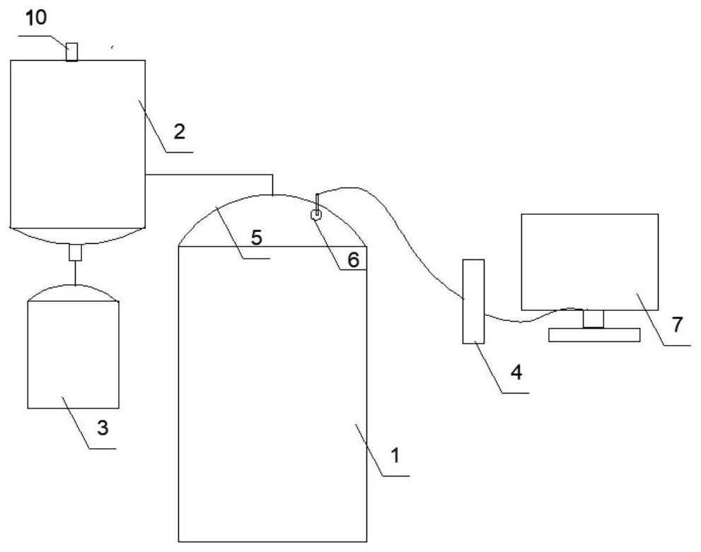
[0017] Such as figure 1 As shown, a vacuum low-temperature dehydration equipment with a monitoring device includes a dehydration reactor 1, a condensation device 2, a condensed water collection device 3 and a monitoring device. The dehydration reactor is provided with a cover 5, and the cover The air outlet on the top is connected to the air inlet of the condensing device through a pipeline, and the drain of the condensing device is connected to the water inlet of the condensed water collecting device through a pipeline. The monitoring device includes a camera 6, a PLC controller 4 and a display 7, The camera is arranged on the cover in the dehydration reactor, and the camera and the display are electrically connected with the PLC controller.

[0018] The model of the PLC controller used in this embodiment is S7-400, which is suitable for the field of medium and high performance automation control, with powerful performance and simple operation.

Embodiment 2

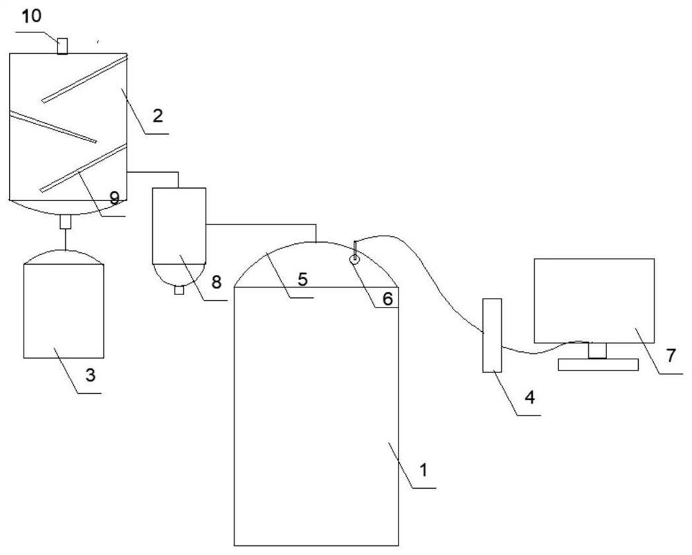
[0020] Such as figure 2 As shown, a vacuum low-temperature dehydration equipment with a monitoring device includes a dehydration reactor 1, a condensation device 2, a condensed water collection device 3 and a monitoring device. The dehydration reactor is provided with a cover 5, and the cover The air outlet on the top is connected to the air inlet of the condensing device through a pipeline, and the drain of the condensing device is connected to the water inlet of the condensed water collecting device through a pipeline. The monitoring device includes a camera 6, a PLC controller 4 and a display 7, The camera is arranged on the cover in the dehydration reactor, and the camera and the display are electrically connected with the PLC controller.

[0021] An oil-gas separator 8 is arranged between the air outlet on the cover and the air inlet of the condensing device, the air inlet of the oil-air separator is connected with the air outlet on the cover through a pipeline, and the ...


PUM


Abstract

The invention belongs to the technical field of dehydration equipment, and particularly relates to vacuum low-temperature dehydration equipment with a monitoring device, wherein the vacuum low-temperature dehydration equipment comprises a dehydration reaction kettle, a condensing device, a condensed water collecting device and the monitoring device, and an air outlet on a cover body of the dehydration reaction kettle is connected with an air inlet of the condensing device through a pipeline; a water outlet of the condensing device is connected with a water inlet of the condensed water collecting device through a pipeline; the monitoring device comprises a camera, a controller and a displayer, the camera is arranged on the cover body in the dehydration reaction kettle, and the camera and the displayer are electrically connected with the controller. According to the equipment, the camera is additionally arranged on the cover body in the reaction kettle, the camera can send the monitoredcondition in the reaction kettle in the food dehydration processing operation process to the controller, and the controller sends a received video signal to the displayer in time to be displayed; a worker can conveniently know the processing state of food in the reaction kettle in time, and use and operation are more convenient.

Description

technical field [0001] The invention belongs to the technical field of dehydration equipment, in particular to a vacuum low-temperature dehydration equipment with a monitoring device. Background technique [0002] Vacuum low-temperature dehydration equipment is a type of food dehydration equipment commonly used in the field of food processing. In vacuum low-temperature dehydration equipment, part of the water in food evaporates in a vacuum. Cooling uses the principle of water evaporation and heat absorption. In the vacuum system, the air content per unit volume is lower than that in the atmosphere. Food processing in this relatively anoxic state can reduce or even avoid the harm caused by oxidation, such as fatty acid breakdown, enzymatic Browning or other oxidative deterioration, etc. [0003] Vacuum low-temperature dehydration equipment in the prior art is mostly composed of a dehydration reactor, a condensation device, and a condensed water collection device. When perfo...

Claims


Application Information

Patent Timeline
Patent Type & Authority Applications(China)
IPC IPC(8): B01D1/00B01D1/30B01J3/00
CPCB01D1/0082B01D1/30B01J3/002B01J3/006
Inventor 朱成栋
Owner 山东立威微波设备有限公司
Features
  • R&D
  • Intellectual Property
  • Life Sciences
  • Materials
  • Tech Scout
  • Unparalleled Data Quality
  • Higher Quality Content
  • 60% Fewer Hallucinations
Learn More