Vibration box of block making machine

A block forming machine and vibration box technology, applied in ceramic forming machines, auxiliary forming equipment, manufacturing tools, etc., can solve the problems of not being able to be used as mold vibration, breakage, insufficient vibration, etc., and achieve good vibration effect, simple maintenance, and easy to use convenient effect

Pending Publication Date: 2021-02-05
阮思忠
View PDF0 Cites 0 Cited by
  • Summary
  • Abstract
  • Description
  • Claims
  • Application Information

AI Technical Summary

Problems solved by technology

[0002] In the existing traditional cement brick forming machine vibration box structure, a row of eccentric shafts is arranged at the bottom of a platform. The defect is that the small machine can only arrange two, and this method can only be used as a table earthquake and not as a model earthquake. , the eccentric shaft is more eccentric and the shaft is prone to breakage, and the vibration effect is not good due to high amplitude
If the eccentricity of the eccentric shaft is small, it often leads to insufficient vibration, and the table vibration will never achieve the effect of model vibration
It is also impossible to achieve synchronous vibration of the table model

Method used


Image

  • Vibration box of block making machine
  • Vibration box of block making machine
  • Vibration box of block making machine

Examples


Embodiment approach

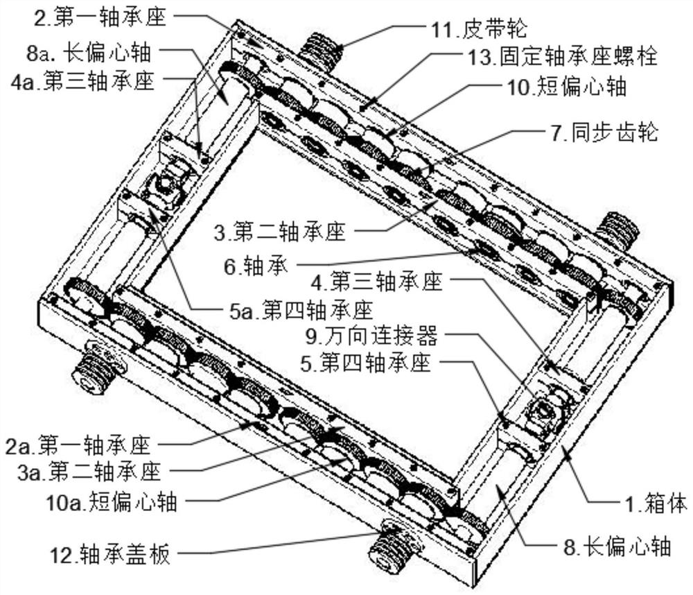
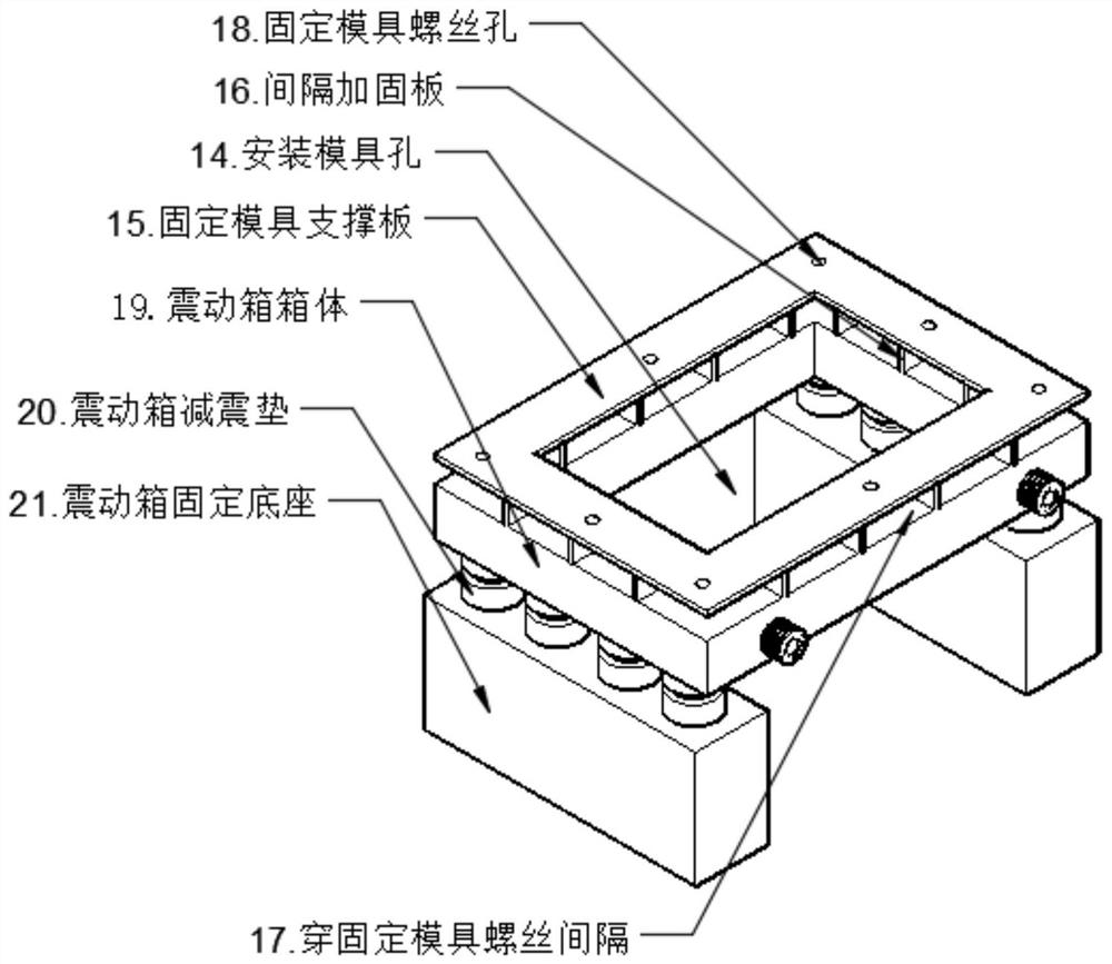
[0021] Such as figure 1 As shown, according to one embodiment of the present invention, the vibrating box of the block forming machine of the present invention is divided into front, rear, left, and right sides including a box body 1, and the middle part of the box body 1 is provided with an installation through hole 14 for installing block mold. Such as image 3 As shown, according to one embodiment of the invention, the installation through hole 14 can be set in a rectangular or square hole shape.

[0022] In the present invention, along the figure 1 The shown box body 1 is symmetrically provided with the first bearing seat (2, 2a), the second bearing seat (3, 3a), the first bearing seat (2, 2a), the second bearing seat (3, 3a) A plurality of short eccentric shafts (10, 10a) are connected to the top, and synchronous gears 7 and bearings 6 are arranged on the short eccentric shafts. A third bearing seat (4, 4a) and a fourth bearing seat (5, 5a) are symmetrically arranged ...


PUM


Abstract

The invention relates to a vibration box of a block making machine. The vibration box of the block making machine comprises a box body, wherein the box body is divided into a front direction, a rear direction, a left direction and a right direction; short eccentric shafts are arranged in the front direction and the rear direction; long eccentric shafts are arranged in the left direction and the right direction; a through hole for installing a mold is formed in the middle of the box body; bearing seats, eccentric shafts, bearings and synchronous gears are arranged around the box body; the firstbearing seats and the second bearing seats are arranged in the front-back symmetrical direction of the mounting through hole; a plurality of short eccentric shafts are connected onto the first bearing seats and the second bearing seats; a plurality of long eccentric shafts are connected onto the third bearing seats and the fourth bearing seats on the left side and the right side; the long eccentric shafts are connected in the length direction through universal connectors; the short eccentric shafts and the long eccentric shafts are connected through the synchronous gears to form synchronization; the two or four short eccentric shafts extend out of the box body; belt wheels are installed; and the eccentric shafts are driven by the motor belt wheels so as to generate synchronous vibration.The vibration box of the block making machine provided by the invention is good in vibration effect.

Description

technical field [0001] The invention relates to a component of a cement brick block forming machine, in particular to a vibration box of a block forming machine. Background technique [0002] In the existing traditional cement brick forming machine vibration box structure, a row of eccentric shafts is arranged at the bottom of a platform. The defect is that the small machine can only arrange two, and this method can only be used as a table earthquake and not as a model earthquake. , the eccentric shaft is prone to fracture if the eccentric shaft is large, and the vibration effect is not good if the amplitude is high. If the eccentricity of the eccentric shaft is small, it often leads to insufficient vibration, and the table vibration will never achieve the effect of model vibration. It is also impossible to achieve synchronous table mold combined vibration. Contents of the invention [0003] The object of the present invention is to solve the above problems and provide a...

Claims


Application Information

Patent Timeline
Patent Type & Authority Applications(China)
IPC IPC(8): B28B1/087B28B17/00
CPCB28B1/0873B28B17/00
Inventor 阮思忠
Owner 阮思忠
Why Eureka
Try Eureka