
Roadway U-shaped support device and method

A technology of support device and roadway, which is applied to pillars/supports, earthwork drilling, mining equipment, etc., can solve the problems of increasing support costs, uneven stress on supports, deformation of surrounding rock, etc. Self-stabilizing ability, controlling the effect of early deformation

Pending Publication Date: 2021-02-05
NORTHEASTERN UNIV +1
View PDF5 Cites 3 Cited by
  • Summary
  • Abstract
  • Description
  • Claims
  • Application Information

AI Technical Summary

Problems solved by technology

[0003] 1. The actual support capacity is far lower than the theoretical support capacity: When the load borne by the support has not reached its limit load, structural damage occurs and the support fails
Relevant researchers have found through the statistics and analysis of a large number of engineering cases that the main reason for this phenomenon is that due to the existence of over-excavation and under-excavation, there are many and large gaps between the erection bracket and the surrounding rock after excavation of the roadway. The top effect is poor, and the bracket and the surrounding rock often have random point and line contacts with each other, so that the whole bracket is unevenly stressed after the surrounding rock is deformed and compressed, and the stress concentration in the bracket structure is caused by local load and eccentric load. Early failure of the stent
[0004] 2. Passive support limits its load-bearing performance: U-shaped steel retractable support is in contact with the surrounding rock of the roadway after erection, but it does not produce any active support force on the surrounding rock, but passively waits for the deformation of the surrounding rock to squeeze the support It is a typical "passive support" and cannot effectively control the early deformation of the surrounding rock, which limits the full play of the bearing capacity of the surrounding rock itself.
[0005] 3. The legs of the support sink into the bottom plate: This problem is more obvious in soft rock roadways, especially in projects with low floor strength. After the support is erected, the contact area between the legs and the bottom plate is small. When the load is applied, the stress generated by the contact between the legs and the bottom plate is greater than the strength of the bottom plate, and the legs of the bracket will sink into the bottom plate, which will cause excessive deformation of the surrounding rock and cause support failure
However, the high price of hydraulic equipment used in this method greatly increases the support cost, and the hydraulic equipment erected inside the support occupies a large amount of space, which greatly reduces the usable cross-sectional area of ​​the roadway, which is not conducive to the passage of underground equipment personnel.
[0010] For the problem that the legs of the bracket sink into the bottom plate, the most effective method is to weld a steel plate with a certain thickness on the leg of the bracket to increase the contact area between the legs of the bracket and the bottom plate. Considering that the steel plate should be evenly stressed, the leg of the bracket Usually welded in the center of the steel plate, it will inevitably cause a large gap between the legs of the support and the surrounding rock of the two sides of the roadway, which will affect the control of the deformation of the two sides of the surrounding rock by the support.
[0011] In the above-mentioned schemes, most of them use the method of improving the stress state of the bracket to improve the load-bearing performance of the U-shaped steel bracket, which is still passive support and fails to take advantage of the advantages of active support; in the scheme with active support characteristics, it is based on Complicated process, high cost, or sacrificing the utilization rate of the roadway section has no advantages in terms of economy and feasibility; the above-mentioned scheme does not fully consider the basic mechanical properties of the surrounding rock when performing active support with U-shaped steel brackets , and the relationship between surrounding rock, support and active support force, it is impossible to achieve a good support effect

Method used


Image

  • Roadway U-shaped support device and method
  • Roadway U-shaped support device and method

Examples


Embodiment Construction

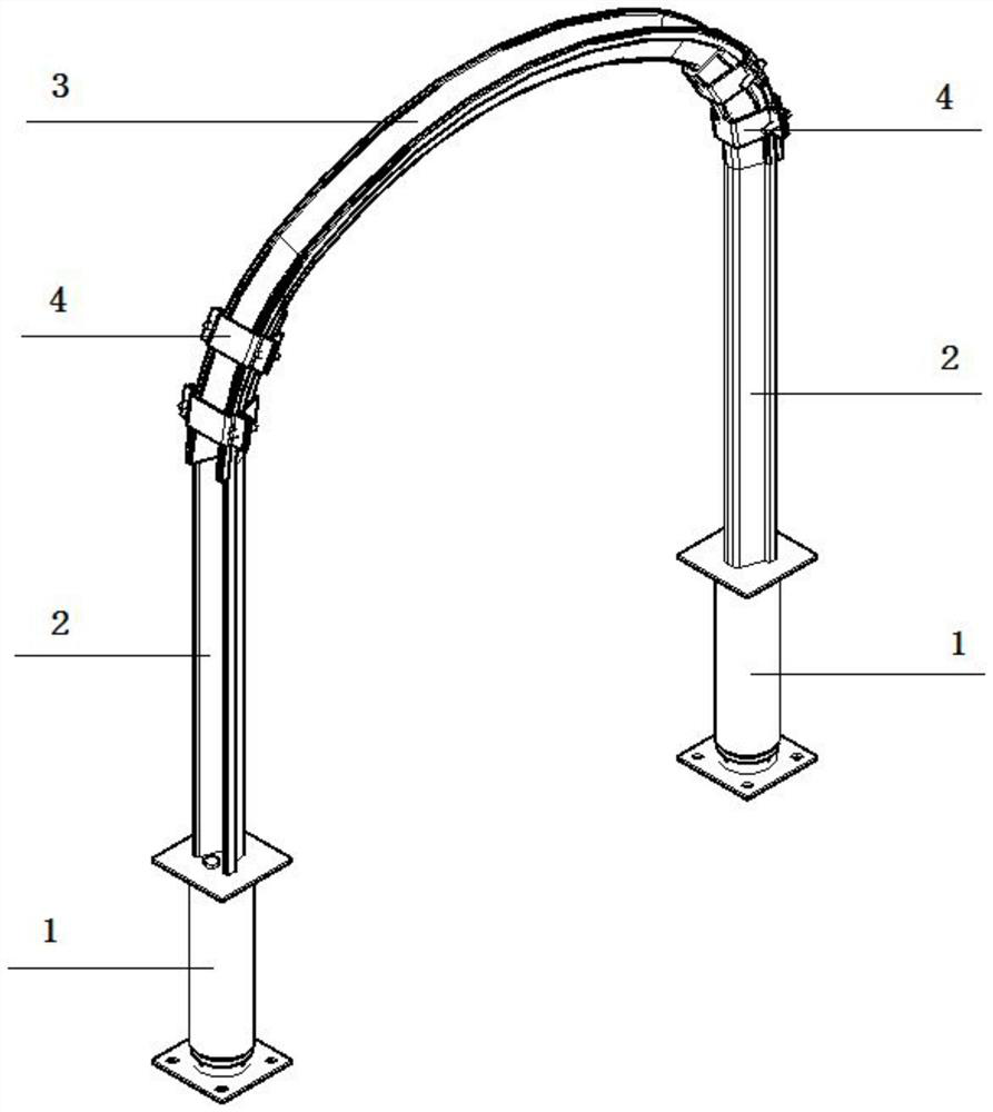
[0055] The present invention will be further described in detail below in conjunction with the accompanying drawings and specific usage methods.

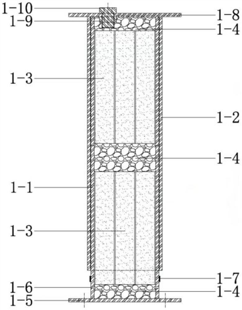
[0056]Working principle: in the inner space of the lower inner sleeve 1-1 of the bracket leg expansion device 1, lay the filled river sand 1-4 and bundle-shaped composite expansion material medicine rolls in a certain order, and the U-shaped steel of the bracket leg is welded on the cover The upper outer sleeve 1-2 of 2 connects the overlapping parts between the U-shaped steel 3 of the bracket vault and the U-shaped steel 2 of the bracket leg through the connection card cable 4 and applies the designed pretightening force to form the overall structure of the U-shaped steel; The elastic rubber ring 1-7 seals the drainage vent hole 1-6 under the lower inner sleeve 1-1 body, and fills the river sand 1 into the support leg expansion device 1 through the water injection hole 1-8. -4 and the space of bundle-shaped composite expansion mate...


PUM


Abstract

The invention relates to a roadway U-shaped support device and method. The roadway U-shaped support device comprises support vault U-shaped steel, support leg U-shaped steel is fixedly connected to the two ends of the support vault U-shaped steel through connecting clamping cables, and a support leg expansion device is arranged at the bottom of the support leg U-shaped steel; the support leg expansion device comprises a lower inner sleeve, an upper outer sleeve, a bundle-shaped composite expansion material cartridge and filling river sand; and the upper outer sleeve sleeves the lower inner sleeve, the bundle-shaped composite expansion material cartridge is arranged in the lower inner sleeve, and the filling river sand is arranged at the top and the bottom of the bundle-shaped composite expansion material cartridge. The overall stress state of the U-shaped support can be effectively improved, load-controllable initial supporting force can be provided for surrounding rock, the function of adapting to surrounding rock deformation is achieved, the column leg structure is good in bending resistance, the column leg strength is high, the structure is simple, the cost is low, the construction process is simple, and the roadway section utilization rate is not affected.

Description

technical field [0001] The invention belongs to the technical field of underground mine roadway and geotechnical engineering tunnel support, and in particular relates to a roadway U-shaped support device and method. Background technique [0002] With more and more underground mines entering deep mining in our country, and the implementation of a large number of deep geotechnical engineering, the high stress environment in the deep place puts forward higher requirements for the support technology. The U-shaped steel shrinkable support has been widely used in the support of mine roadways, railway tunnels and other underground geotechnical engineering tunnels at home and abroad because of its strong bearing capacity and compressible support. Gradually expand from soft rock roadway to hard rock roadway. Due to the complexity and diversity of engineering situations, in practical engineering applications, the following problems often arise: [0003] 1. The actual support capacit...

Claims


Application Information

Patent Timeline
IPC IPC(8): E21D15/02E21D15/50E21D15/55
CPCE21D15/02E21D15/50E21D15/55
Inventor 李元辉戴星航李坤蒙安龙冯夏庭
Owner NORTHEASTERN UNIV
Learn More