Control method and system for improving frequency and power of free piston linear generator

A technology of linear generators and control methods, applied in free piston engines, engine control, machines/engines, etc., can solve the problems of less than 1.1kW output power, low maximum moving speed of movers, and low overall operating frequency, and achieve improved The effect of improving the movement frequency of the mover, reducing the pump air loss and increasing the working frequency

Active Publication Date: 2021-02-05
ZIBO SUPER MOTOR
View PDF8 Cites 0 Cited by
  • Summary
  • Abstract
  • Description
  • Claims
  • Application Information

AI Technical Summary

Problems solved by technology

For another example, a single-cylinder two-stroke engine with an effective piston stroke of 39.8mm, a cylinder bore of 40mm, and an engine displacement of 49.9ml can have a maximum output power of 3.0kW when the operating frequency is about 125Hz, but when the operating frequency is about 40Hz , its output power is less than 1.1kW
Leading to problems such as low maximum movement speed of the mover, long stroke running time, and low overall working frequency

Method used


Image

  • Control method and system for improving frequency and power of free piston linear generator
  • Control method and system for improving frequency and power of free piston linear generator
  • Control method and system for improving frequency and power of free piston linear generator

Examples


Embodiment 1

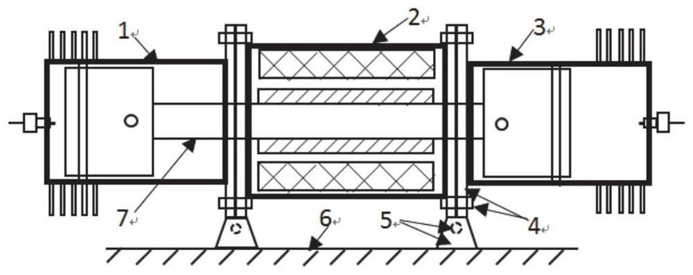
[0038] This embodiment discloses a control method for increasing the frequency and power of a free-piston linear generator, including:

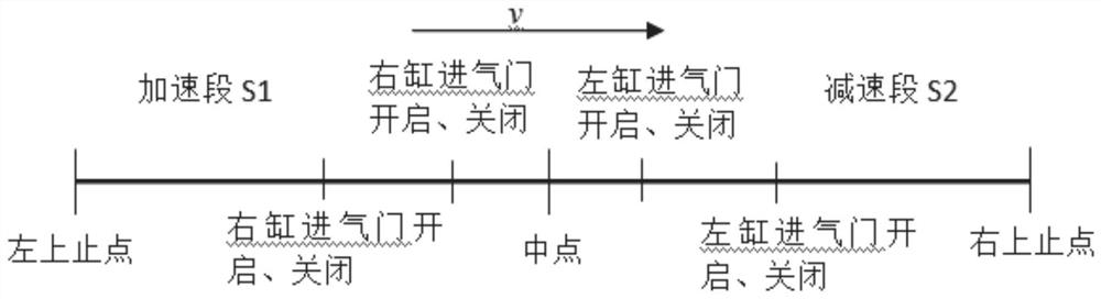
[0039] Moving the mover from the top dead center position on one side to the top dead center position on the other side is divided into an acceleration section and a deceleration section, where the stroke length of the mover acceleration section S 1 and the stroke length S of the deceleration section of the mover 2 The sum is a fixed value;

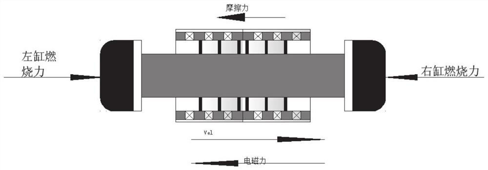
[0040] In the acceleration section, the electromagnetic load is the resistance. By reducing the electromagnetic load of the motor, the acceleration of the mover in this stage is increased, and the acceleration section S is reduced. 1 travel time;

[0041] In the deceleration section, the size of the electromagnetic load is controlled so that the travel S of the mover in this section 2 Complete the action from a certain movement speed to zero in the middle, shorten the deceleration stage time.

[0042...

Embodiment 2

[0129] The purpose of this embodiment is to provide a computing device, including a memory, a processor, and a computer program stored in the memory and operable on the processor. When the processor executes the program, the method in the first embodiment above is realized. step.

Embodiment 3

[0131] The purpose of this embodiment is to provide a computer-readable storage medium.

[0132] A computer-readable storage medium, on which a computer program is stored. When the program is executed by a processor, the steps of the method in the first embodiment above are performed.


PUM


Abstract

The invention provides a control method and system for improving the frequency and power of a free piston linear generator. The method comprises the steps that the movement of a rotor from an upper dead center position at one side to an upper dead center position at the other side is divided into an acceleration section and a deceleration section, wherein the sum of the stroke length of the acceleration section of the rotor and the stroke length of the deceleration section of the rotor is a fixed value; in the acceleration section, the electromagnetic load is resistance, and by reducing the electromagnetic load of a motor, the acceleration of the rotor in the stage is increased and the stroke time of the acceleration section is shortened; and in the deceleration section, the electromagnetic load is controlled to enable the rotor to finish the action of reducing a certain motion speed to zero in the stroke of the section, so that the time of the deceleration section is shortened. On thebasis of sectional control over the size and waveform of the electromagnetic load, under the condition that other conditions are not changed, (1) the working frequency is improved, and then the system output power is improved; and (2) the output power and the working frequency of the system are adjusted according to load requirements, throttle-valve-free control is realized, and the pumping lossis reduced.

Description

technical field [0001] The disclosure belongs to the technical field of range extenders for new energy vehicles, and in particular relates to a control method and system for increasing the frequency and power of a free-piston linear generator. Background technique [0002] The statements in this section merely provide background information related to the present disclosure and do not necessarily constitute prior art. [0003] The free-piston linear generator (FPLG) converts the heat energy generated by the combustion engine into electrical energy output through the motor, which can replace the auxiliary power unit (APU) of the range-extended hybrid electric vehicle. As an emerging power device, the free-piston linear generator is An important research direction of the future new energy vehicle power system. [0004] The internal combustion engine in the FPLG system has similar thermodynamic principles to the traditional internal combustion engine, but the crank linkage mec...

Claims


Application Information

Patent Timeline
Patent Type & Authority Applications(China)
IPC IPC(8): F02B71/00F02B71/04F02B71/02F02D29/06
CPCF02B71/00F02B71/02F02B71/04F02D29/06
Inventor 唐娟程勇马宗正吕宏马翠英
Owner ZIBO SUPER MOTOR
Why Eureka
Try Eureka