
Silicon-based micro-ring pulse coding time division multiplexing dynamic wavelength demodulation method

A technology of pulse coding and time division multiplexing, which is applied in the field of optical communication, and can solve the problems that dynamic testing cannot be realized.

Active Publication Date: 2021-02-05
SHANGHAI JIAO TONG UNIV
View PDF7 Cites 2 Cited by
  • Summary
  • Abstract
  • Description
  • Claims
  • Application Information

AI Technical Summary

Problems solved by technology

However, this technology cannot realize dynamic testing

Method used


Image

  • Silicon-based micro-ring pulse coding time division multiplexing dynamic wavelength demodulation method
  • Silicon-based micro-ring pulse coding time division multiplexing dynamic wavelength demodulation method
  • Silicon-based micro-ring pulse coding time division multiplexing dynamic wavelength demodulation method

Examples


Embodiment Construction

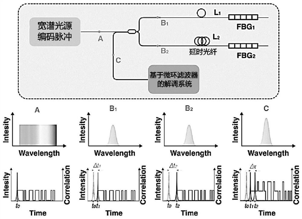
[0023] Such as figure 1 As shown, this embodiment relates to a pulse compression time-division multiplexing system based on optical pulse coding, including: a broadband coded optical pulse generation unit, an integrated demodulation unit, and a first FBG connected to it through the first optical fiber L1 It is connected to the second FBG through the delay fiber L3, wherein: the original wide-spectrum light source coded pulse is split by the fiber coupler and then input to the FBG sensors of different channels, and the delay fiber adds a delay to the reflected signal of the second FBG, and the fiber The coupler feeds the reflected pulse into a microring filter-based demodulation system.

[0024] The parameters of the first FBG and the second FBG are the same, and different time delays are realized through the time-delay optical fiber; as shown in the figure: after the reflected encoding pulses of the two FBG sensors are transmitted through the time-delay optical fibers of diffe...


PUM


Abstract

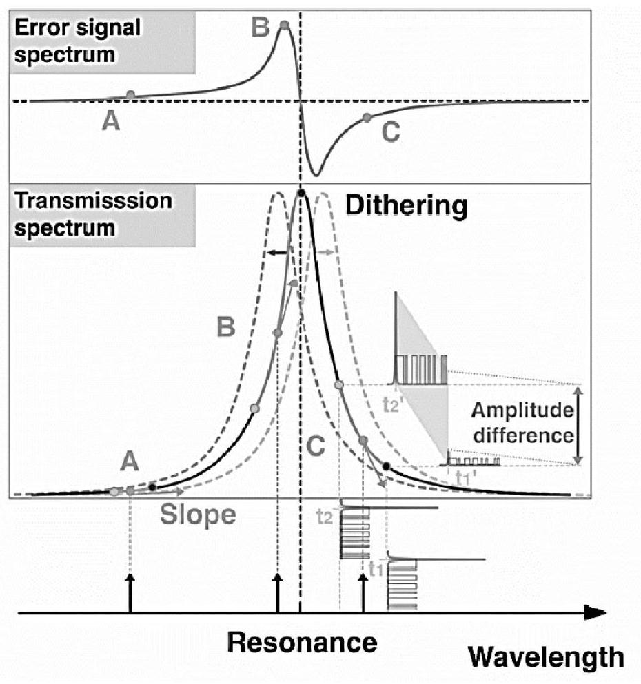
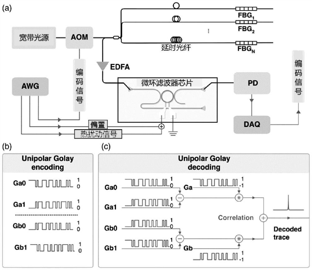
The invention relates to a silicon-based micro-ring pulse coding time division multiplexing dynamic wavelength demodulation method, which comprises the following steps: performing pulse coding on wide-spectrum light by adopting acousto-optic modulation, sending the processed light to an FBG sensor, coupling an FBG reflection signal to a micro-ring filter chip through an optical fiber coupler, andperforming modulating by applying a thermal disturbance signal to the micro-ring filter chip; and enabling a receiving terminal to extract a sensing signal through an electric signal obtained by photoelectric detection by adopting a slope-assisted micro-ring filtering demodulation algorithm. According to the invention, the micro-ring filter is used for detecting the Bragg wavelength drift of the FBG sensor, thereby achieving the signal demodulation of the silicon-based integrated time division multiplexing FBG sensor.

Description

technical field [0001] The present invention relates to a technology in the field of optical communication, in particular to a silicon-based microring pulse encoding time-division multiplexing dynamic wavelength demodulation method for fiber grating sensors, which can be applied to multiple time-division in encoding pulse sensing systems Integrated sensing signal extraction for multiplexed channels. Background technique [0002] The optical fiber sensing system consists of two parts: an optical sensor and a sensing signal detection system. The existing optical sensing detection system is composed of discrete devices, but its disadvantages are large volume and high cost. The existing mainstream integrated FBG sensing detection system is mainly based on spectral analysis, interferometry, and filtering methods. However, due to the size of key devices and system demodulation methods, the scalability of spectral analysis and interferometry is poor. The accuracy of the filtering...

Claims


Application Information

Patent Timeline
IPC IPC(8): G01D5/26
CPCG01D5/268
Inventor 张文甲何祖源杨帆
Owner SHANGHAI JIAO TONG UNIV
Learn More