
Motor rotating speed TTL signal generation method, device and system for magnetic suspension bearing control

A technology of magnetic suspension bearing and motor speed, applied in control systems, magnetic bearings, bearings, etc., can solve the problems of increasing the overall cost of the system and the overall complexity of the system, and avoid the hardware cost and system complexity. There is no phase error or Offset, high precision effects

Active Publication Date: 2021-02-05
ZHUZHOU NAT ENG RES CENT OF CONVERTERS
View PDF4 Cites 0 Cited by
  • Summary
  • Abstract
  • Description
  • Claims
  • Application Information

AI Technical Summary

Problems solved by technology

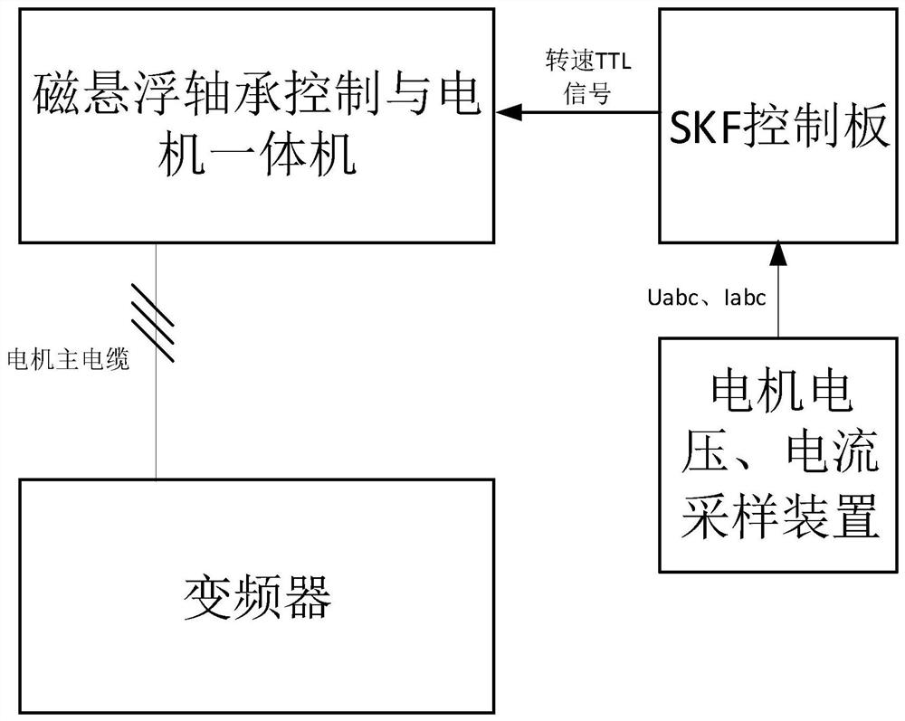
SKF collects the motor voltage and current through a control board to calculate the corresponding speed TTL signal. The structure of the control system is as follows: figure 2 Shown: According to the configuration of SKF, SKF control board, current sensor and other components need to be added, which will increase the overall cost and complexity of the system

Method used


Image

  • Motor rotating speed TTL signal generation method, device and system for magnetic suspension bearing control
  • Motor rotating speed TTL signal generation method, device and system for magnetic suspension bearing control
  • Motor rotating speed TTL signal generation method, device and system for magnetic suspension bearing control

Examples


Embodiment 1

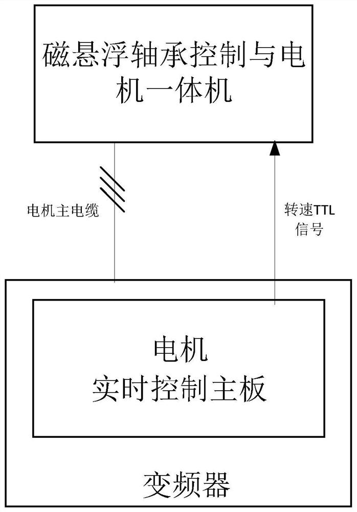
[0038] Such as image 3 As shown, the motor speed TTL signal generation method for magnetic suspension bearing control in this embodiment includes the following steps:

[0039] S01. Obtain the phase angle of the output voltage of the motor, wherein the phase angle is a process quantity in the real-time control algorithm of the motor in the frequency converter;

[0040] S02. Comparing the phase angle with a preset K value to generate a rotational speed TTL signal; when the phase angle is greater than the preset K value, the TTL signal output is 1, otherwise the TTL signal output is 0. The K value can be selected according to the actual situation.

[0041] The present invention does not add any parts and equipment to the frequency converter, and directly generates a speed TTL signal (pulse width at the level of 100us) through the real-time control of the main board of the frequency converter motor and its real-time control algorithm, and the high real-time TTL signal controls t...

Embodiment 2

[0052] The motor speed TTL signal generation method for magnetic suspension bearing control in this embodiment includes the following steps:

[0053] S01. Obtain the motor output voltage phase angle; the specific process is:

[0054] S11. Acquiring the rotational speed signal output by the frequency converter;

[0055] S12. Obtain the motor output voltage phase angle through the rotational speed signal;

[0056] S02. According to the comparison between the phase angle and the preset K value, a rotational speed TTL signal is generated; where the phase angle is greater than the preset K value, the TTL signal output is 1, otherwise the TTL signal output is 0. The K value can be selected according to the actual situation.

[0057] In this embodiment, the specific process of step S12 is:

[0058] S121, converting the rotational speed signal into a mechanical angular frequency velocity;

[0059] S122, converting the mechanical angular frequency velocity into the electrical angul...


PUM


Abstract

The invention discloses a motor rotating speed TTL signal generation method, device and system for magnetic suspension bearing control, a medium and equipment. The method comprises the steps: acquiring a motor output voltage phase angle; comparing the phase angle with a preset K value to generate a rotating speed TTL signal, wherein when the phase angle is greater than a preset K value, the TTL signal output is 1, otherwise, the TTL signal output is 0. The motor rotating speed TTL signal generation method, device and system for magnetic suspension bearing control, the medium and the equipmenthave the advantages of being low in cost, good in real-time performance, high in precision and the like.

Description

technical field [0001] The invention mainly relates to the technical field of magnetic suspension bearings, in particular to a method, device and system for generating TTL signal of motor speed for magnetic suspension bearing control. Background technique [0002] The magnetic levitation centrifugal refrigeration compressor has high efficiency, low noise and high reliability, representing the most advanced technology of centrifugal compressors in the world. After the traditional bearing is replaced by the magnetic suspension bearing technology, no lubricating oil is required, the noise is ultra-low and the friction loss is reduced. Magnetic suspension bearing control basically requires the motor speed TTL signal for bearing control compensation, in which the motor speed TTL signal is mainly used for the rotor mass imbalance control in the magnetic suspension bearing control, so as to suppress the same frequency of the rotor caused by the rotor mass imbalance (with the motor ...

Claims


Application Information

Patent Timeline
Patent Type & Authority Applications(China)
IPC IPC(8): H02P27/04H02P23/00F16C32/04
CPCH02P27/04H02P23/0004F16C32/044
Inventor 秦灿华何亚屏成正林张哲曾小凡奥恩韩志成文亮邓明李嘉罗何杨卓孟文辉王嘉义周奔李宇李易邓德新何林桂
Owner ZHUZHOU NAT ENG RES CENT OF CONVERTERS
Learn More