A Fast Fault Diagnosis Control Method of Position Square Wave Signal of Switched Reluctance Motor

A switched reluctance motor, square wave signal technology, applied in the direction of motor control, control system, electrical components, etc., can solve the problems of lag in diagnosis results, winding current burning controller, rotor position angle confusion, etc., to achieve system reliability and reliability. Improve fault tolerance, good versatility and portability, and solve the effect of complex diagnosis algorithms

Active Publication Date: 2022-05-20
NANJING UNIV OF INFORMATION SCI & TECH
View PDF7 Cites 0 Cited by
  • Summary
  • Abstract
  • Description
  • Claims
  • Application Information

AI Technical Summary

Problems solved by technology

These four position square wave signal failures will increase the calculation error of the rotor position angle of the switched reluctance motor, and in severe cases, the calculated rotor position angle will be confused, resulting in confusion of the drive signals of each phase of the switched reluctance motor
The confusion of the drive signal will lead to a sudden increase or decrease in the motor speed, or even a stall. In addition, a sharp increase in the winding current will burn the controller
Therefore, if the position signal cannot achieve accurate and fast fault diagnosis, the reliability and fault tolerance of the switched reluctance motor drive system will be greatly reduced
The traditional position signal fault diagnosis method can realize the fault diagnosis of position signal, but there are usually problems such as complex diagnosis algorithm, lagging diagnosis result, unclear diagnosis classification, etc.

Method used


Image

  • A Fast Fault Diagnosis Control Method of Position Square Wave Signal of Switched Reluctance Motor
  • A Fast Fault Diagnosis Control Method of Position Square Wave Signal of Switched Reluctance Motor
  • A Fast Fault Diagnosis Control Method of Position Square Wave Signal of Switched Reluctance Motor

Examples


Embodiment Construction

[0027] The specific implementation manners of the present invention will be further described in detail below in conjunction with the accompanying drawings.

[0028] The present invention designs a fast fault diagnosis control method of a position square wave signal of a switched reluctance motor, including a comprehensive hybrid integral threshold detection logic control method with the fast fault diagnosis and classification capabilities of the position square wave signal, and including a position square wave signal Fault tolerant control method.

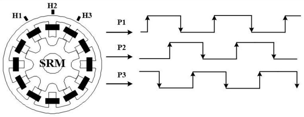
[0029] In practical applications, such as figure 1 As shown, taking the 12 / 8 structure three-phase switched reluctance motor as an example, the schematic diagram of using three photoelectric sensors or Hall sensors to detect the rotor position signal is given. The three position sensors H1-H3 are installed at intervals of 30 degrees from each other, and three position square wave signals of P1-P3 can be obtained, whose rising an...


PUM


Abstract

The invention relates to a fast fault diagnosis control method for a position square wave signal of a switched reluctance motor. Aiming at the position square wave signal detected by a position sensor, a comprehensive mixed integral threshold value detection logic control method is used to realize the fault of the position square wave signal Diagnosis and fault classification, under the steady-state and dynamic operation of the high-speed switched reluctance motor, this method can immediately lock the fault and distinguish the fault type at the moment when the position square wave signal fault occurs; because this method can detect each position sensor The position square wave signal is processed independently, so in the whole position detection system, as long as there is a position square wave signal detected by a position sensor to be normal, the fault-tolerant operation of the motor under the position signal failure mode can be realized; the practical application of the design method of the present invention Among them, the rapidity and real-time performance of fault diagnosis and the accuracy of fault classification have important practical value for improving the fault tolerance of switched reluctance motor system.

Description

technical field [0001] The invention relates to a fast fault diagnosis control method for a position square wave signal of a switched reluctance motor, belonging to the technical field of motor control. Background technique [0002] The real-time and accurate rotor position signal is the key to the operation control of the switched reluctance motor drive. In the switched reluctance motor drive system, position sensors such as Hall sensors and photoelectric sensors are usually used to detect the rotor position. In the sensor and signal conditioning circuit Under normal operation, this type of position sensor outputs a pulse signal with a duty ratio of 0.5 in each electrical cycle of the switched reluctance motor. The position signal detected by the position sensor is a group of square wave signals. However if figure 2 As shown, when the position sensor and the signal conditioning circuit fail, the detected position square wave signal usually has two low-level failure modes ...

Claims


Application Information

Patent Timeline
Patent Type & Authority Patents(China)
IPC IPC(8): H02P29/028H02P6/16
CPCH02P29/028H02P6/16
Inventor 蔡骏
Owner NANJING UNIV OF INFORMATION SCI & TECH
Why Eureka
Try Eureka