
Nano-bubble generating device

A generating device and nano-bubble technology, which is applied in transportation and packaging, sustainable biological treatment, special treatment goals, etc., can solve the problems of small density of bubble distribution, complex structure design, and inability to quickly generate nano-bubbles, etc., to achieve enhanced stability performance, simple structural design, and the effect of extending the flow path

Active Publication Date: 2021-02-09
威海金盛泰科技发展有限公司
View PDF9 Cites 0 Cited by
  • Summary
  • Abstract
  • Description
  • Claims
  • Application Information

AI Technical Summary

Problems solved by technology

[0003] There are still many deficiencies in the existing nano-bubble devices, for example: (1) the structural design is relatively complicated, and the air bubbles are generated by the impact of the water body, and the diameter of the generated bubbles is generally greater than 10 μm; The density is small

Method used


Image

  • Nano-bubble generating device
  • Nano-bubble generating device
  • Nano-bubble generating device

Examples


Embodiment 1

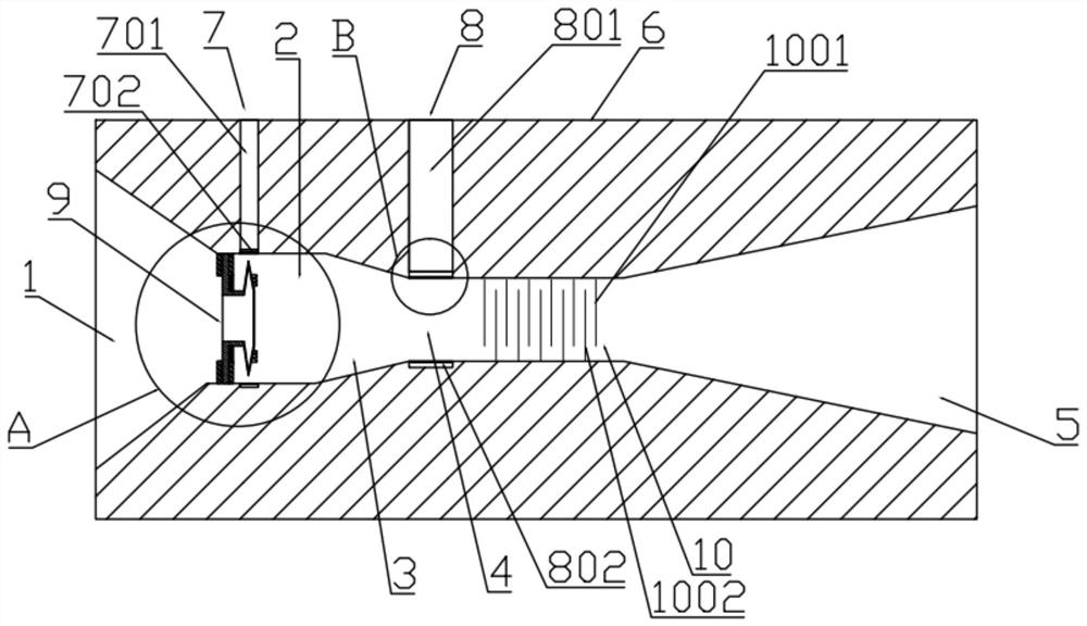
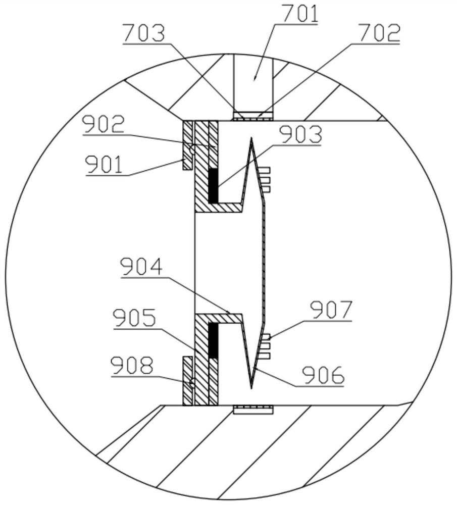
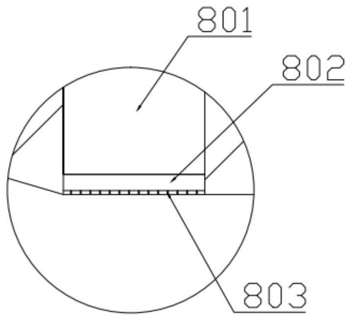
[0025] like Figure 1-5 In the shown embodiment, a nanobubble generating device includes a columnar body 6, and the columnar body 6 is sequentially provided with a first liquid through hole 1, a second liquid through hole 2, a third liquid through hole 3, and a fourth liquid through hole along the axial direction. The liquid through hole 4 and the fifth liquid through hole 5, the first liquid through hole 1 has a tapered structure from the beginning of the columnar body 6 to the second liquid through hole 2, and the second liquid through hole 2 has a cylindrical structure , the third liquid through hole 3 is a tapered structure tapered from the second liquid through hole 2 to the fourth liquid through hole 4, the fourth liquid through hole 4 is a columnar structure, and the fifth liquid through hole 5 is formed by the fourth liquid through hole The conical structure that the liquid through hole 4 reduces to the end of the columnar body 6; the columnar body 6 is provided with a...

Embodiment 2

[0036] The structure of embodiment 2 is basically the same as that of embodiment 1, and its difference is: as Image 6 As shown, the first air intake chamber 701 communicates with the top of the second air intake chamber 801 , and the communicating part communicates with the outside air through the total air intake chamber inclined to the first air intake chamber 701 . According to the Venturi effect, since the diameter of the fourth liquid through hole 4 is smaller than the diameter of the second liquid through hole 2, most of the external air enters the fourth liquid through hole 4 along the second air intake chamber 701 after entering from the total air intake chamber. However, because the inner diameter of the first air intake chamber 701 is smaller than the inner diameter of the second air intake chamber 801, the pressure of the fluid in the first air intake chamber 701 is greater than the pressure of the second air intake chamber 801, and there is also a Venturi effect, s...


PUM


Abstract

The invention relates to the technical field of nano-bubble generating devices, in particular to a nano-bubble generating device. According to the nano-bubble generating device, a columnar main body is sequentially provided with a first liquid through hole, a second liquid through hole, a third liquid through hole, a fourth liquid through hole and a fifth liquid through hole, wherein the first liquid through hole, the third liquid through hole and the fifth liquid through hole are each of a tapered conical structure, and the second liquid through hole and the fourth liquid through hole are each of a columnar structure; a first gas inlet channel communicating with the second liquid through hole and a second gas inlet channel communicating with the fourth liquid through hole are formed in the columnar main body; a gas-liquid cutting and mixing mechanism is arranged at the starting end of the second liquid through hole; and a gas-liquid baffling and dissolving mechanism is arranged in thefourth liquid through hole. According to the invention, air is cut at first, then water mist impact is conducted so as to form nano-bubbles with diameters of about 10 microns, and then bubbles whichenter later collide with the nano-bubbles with the diameters of 10 microns while being impacted by a water body, thereby forming a large number of micro-nano bubbles with diameters in a range of 3-6 microns.

Description

technical field [0001] The invention relates to the technical field of nano-bubble generating devices, in particular to a nano-bubble generating device. Background technique [0002] Micro-bubbles can remain in the water for a long time, so it can increase the dissolved oxygen in water, and due to the existence of micro-bubbles, it can make the fine organic suspended matter in the water (such as corroded dead leaves, algae, etc. in the water body) float on the water surface, and by removing these suspended Substances can promote the purification and revitalization of water bodies. In particular, when the diameter of the bubble is less than 50 microns, the interface of the bubble will be negatively charged, and due to the change of the structure of the water molecules on the interface of the bubble, some free radicals with oxidizing ability will be attached. These free radicals can interact with organic phosphorus and The action of amine nitrogen and the like makes it into a...

Claims


Application Information

Patent Timeline
IPC IPC(8): B01F3/04B01F5/04C02F1/50C02F103/20
CPCC02F1/50C02F2303/04C02F2103/20C02F2103/007C02F2303/26B01F23/291B01F25/31252B01F25/312Y02W10/10
Inventor 李崇敏柳文爽孙鹤铱黄海潮
Owner 威海金盛泰科技发展有限公司
Learn More