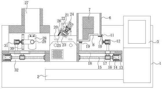
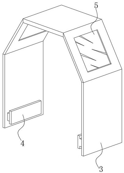
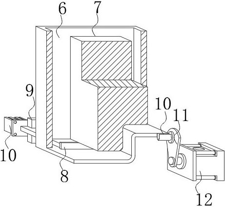
Automobile gear lever producing and machining equipment with positioning function and multi-angle welding function

A processing equipment and multi-angle technology, applied in welding equipment, welding equipment, auxiliary welding equipment, etc., can solve the problems of time-consuming calibration, many operating process steps, time-consuming welding of gear rod and snap ring, etc., to avoid positioning calibration, The effect of speeding up work efficiency

Inactive Publication Date: 2021-02-09
东莞市夯实科技有限公司
View PDF0 Cites 0 Cited by
  • Summary
  • Abstract
  • Description
  • Claims
  • Application Information

AI Technical Summary

Problems solved by technology

[0004] Aiming at the deficiencies of the prior art, the present invention provides a production and processing equipment for automobile gear levers with positioning and multi-angle welding, which solves the problem that the snap ring and the gear lever need to be aligned when they are installed on the fixed frame proposed in the above-mentioned background technology. Calibration, so that there are many operating process steps and time-consuming calibration, so the welding between the gear lever and the snap ring is very time-consuming and other issues

Method used


Image

  • Automobile gear lever producing and machining equipment with positioning function and multi-angle welding function
  • Automobile gear lever producing and machining equipment with positioning function and multi-angle welding function
  • Automobile gear lever producing and machining equipment with positioning function and multi-angle welding function

Examples


Embodiment Construction

[0028] The following will clearly and completely describe the technical solutions in the embodiments of the present invention with reference to the accompanying drawings in the embodiments of the present invention. Obviously, the described embodiments are only some, not all, embodiments of the present invention.

[0029]In the description of the present invention, unless otherwise stated, the meaning of "plurality" is two or more; the terms "upper", "lower", "left", "right", "inner", "outer" , "front end", "rear end", "head", "tail", etc. indicate the orientation or positional relationship based on the orientation or positional relationship shown in the drawings, and are only for the convenience of describing the present invention and simplifying the description, rather than indicates or implies that the device or element referred to must have a particular orientation, be constructed and operate in a particular orientation, and therefore should not be construed as limiting the ...


PUM


Abstract

The invention discloses automobile gear lever producing and machining equipment with the positioning function and the multi-angle welding function. The equipment comprises a bottom rack, a protectivecover is arranged on the right side surface of the bottom rack, and a gear lever feeding box is fixedly welded to the position, located at the left side of the protective cover, of the right side of the center line of the upper surface of the bottom rack; and a clamping ring feeding box is arranged above the left side of the surface of the bottom rack, and a second pushing assembly is arranged atthe bottom of an inner cavity of the bottom rack. According to the equipment, the gear lever feeding box and the clamping ring feeding box are oppositely arranged at the two sides of the surface of the bottom rack, through arrangement of the gear lever feeding box and the clamping ring feeding box, an automatic feeding structure is conveniently formed for a gear lever and a clamping ring, positioning and calibration after manual feeding by personnel are avoided, and meanwhile, a welding machine box and a welding head are arranged in the space between the gear lever feeding box and the clampingring feeding box, so that the gear lever and the clamping ring can be conveniently matched for welding, the working efficiency is favorably improved, and an automatic structure is formed.

Description

technical field [0001] The invention relates to the technical field of automobile gear levers, in particular to a production and processing equipment for automobile gear levers capable of positioning and multi-angle welding. Background technique [0002] The car gear lever is one of the important parts in the car transmission. The gear lever is also called the operating lever. Its main function is to support the car's shifting operation. With the development of the car, the gear lever is also mainly used for manual transmission cars. In the middle, the gear lever cooperates with the shift fork and the shift shaft fork, and the shift operation is formed by manual back and forth fluctuations. [0003] When the car gear lever is assembled with the transmission, a snap ring is needed for connection, and the general shape of the gear lever is horizontal and bent. However, when the Z-shaped gear lever is welded and fixed between the snap rings, it needs to be used due to structura...

Claims


Application Information

Patent Timeline
Patent Type & Authority Applications(China)
IPC IPC(8): B23K31/02B23K37/00B23K37/02B23K37/04
CPCB23K31/02B23K37/00B23K37/0211B23K37/0426
Inventor 林镇炜林晓港徐胜群
Owner 东莞市夯实科技有限公司
Why Eureka
Try Eureka