
Water gas production system, production process and control method

A technology of production system and control method, which is applied in the direction of gasification process, separation method, chemical instrument and method, etc., to achieve the effects of small steam consumption, high steam decomposition rate, and reduced emissions

Pending Publication Date: 2021-02-09
张会强
View PDF0 Cites 0 Cited by
  • Summary
  • Abstract
  • Description
  • Claims
  • Application Information

AI Technical Summary

Problems solved by technology

[0004] In view of this, the present invention aims to propose a water gas production system, production process and control method to solve the problem that the prior art still utilizes the traditional water vapor and high-temperature carbon layer reaction to prepare water gas

Method used


Image

  • Water gas production system, production process and control method
  • Water gas production system, production process and control method
  • Water gas production system, production process and control method

Examples


Embodiment 1

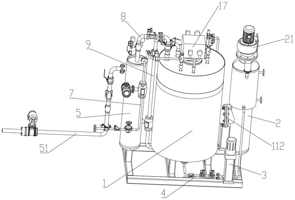
[0066] Since the production system in the prior art still adopts the traditional method of reacting water vapor and high-temperature carbon layer to prepare water gas, not only the steam decomposition rate is low, but the steam consumption is large, and it is easy to pollute the environment. In order to solve this problem, this embodiment proposes a water gas production system. During the operation of the water gas production system, water and alcohol are used as raw material liquids to prepare water gas; specifically:

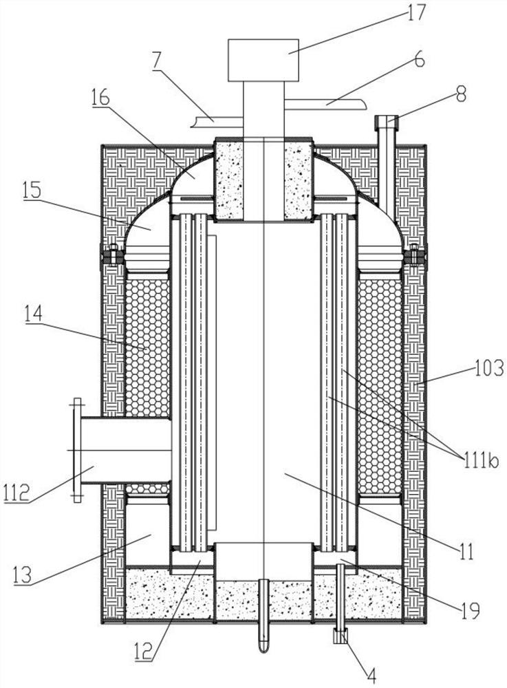
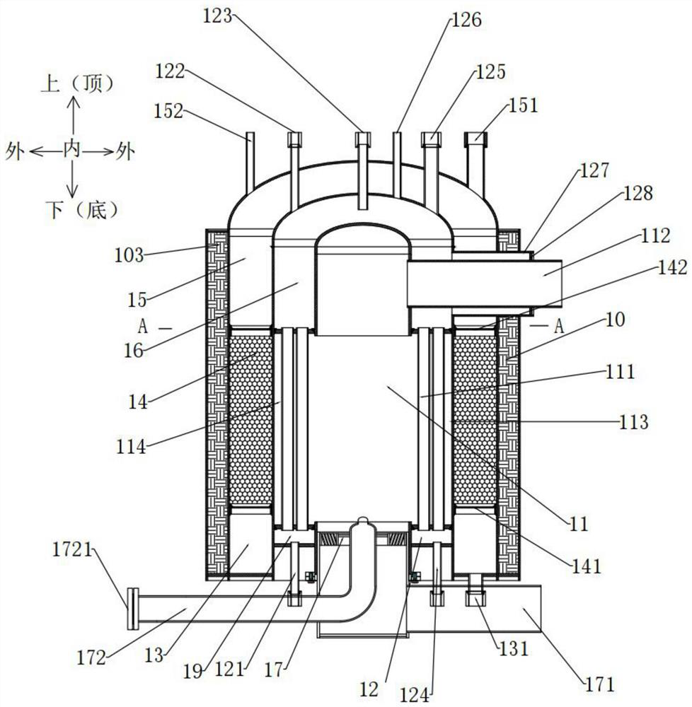
[0067] as attached Figure 1-4 As shown, the production system includes an integrated burner 1, a fan, a liquid storage tank 2, a gas collection device 5, and a fuel supply device. The integrated burner 1 includes at least a combustion chamber 11, a raw material liquid chamber 12, a water gas Preparation room, in the present invention, during the normal operation of the production system, at least the combustion process of fuel and the preparation process of w...

Embodiment approach 2

[0083] For the second embodiment, the raw material liquid chamber 12 may be arranged above the water gas preparation chamber, or may be arranged below the water gas preparation chamber.

Embodiment 2

[0085] Because the catalytic reaction that occurs in the water gas preparation chamber often needs to reach a certain temperature condition, so the application transfers a part of the heat to the water gas preparation chamber by utilizing the combustion process in the combustion chamber 11, so that the water gas preparation chamber can maintain the required temperature. reaction temperature conditions.

[0086] Therefore, in order to maintain the production and preparation process of water gas, the combustion process needs to be maintained in the combustion chamber 11, such as the attached Figure 1-3 As shown, the present embodiment improves the production system on the basis of Embodiment 1:

[0087] The production system includes a fuel supply device and a fuel pipeline 7, the inlet end of the fuel pipeline 7 is connected to the fuel supply device, and the outlet end of the fuel pipeline 7 is connected to the burner 17, so that the integrated burner 1. The internal tempera...


PUM


Abstract

The invention provides a water gas production system, a production process and a control method, the water gas production system uses water and alcohol as raw material liquid to prepare water gas, theproduction system comprises an integrated burner, a fan, a liquid storage tank and a fuel supply device, a combustion process and a water gas preparation process are carried out in the integrated burner at the same time, the fuel supply device is connected with the integrated burner and used for supplying fuel into the integrated burner to maintain the combustion process in the integrated burner,the fan is connected with the integrated burner and used for supplying combustion air to the combustion process, and the liquid storage tank is connected with the integrated burner and used for supplementing raw material liquid into the integrated burner so as to maintain the preparation process of water gas; according to the water gas production system, the production process and the control method, the steam decomposition rate is high, the steam consumption is low, and pollutant emission can be reduced.

Description

technical field [0001] The invention relates to the technical field of production and preparation of synthetic ammonia raw material gas, in particular to a water gas production system, production process and control method. Background technique [0002] Water gas, as the commonly used raw material gas for ammonia synthesis, is used by various small and medium-sized nitrogen fertilizer plants; but at present, most of the existing small and medium-sized nitrogen fertilizer plants in the country use solid anthracite lump coal or briquettes as intermittent gas in fixed-bed gas-making furnaces. Chemical production of synthetic ammonia raw material gas. In the process of gas production, ordinary air (oxygen content ≤ 21%) or oxygen-enriched air (oxygen concentration 45-55%) added with oxygen is generally used as a gasification agent and added to the gas furnace for gas production. When the steam reacts with the high-temperature carbon layer to decompose, it needs to absorb heat, ...

Claims


Application Information

Patent Timeline
Patent Type & Authority Applications(China)
IPC IPC(8): C10J3/48C10J3/50C10J3/52C10J3/56C10J3/60C10J3/62C10J3/66B01D46/10
CPCB01D46/10C10J3/48C10J3/50C10J3/52C10J3/56C10J3/60C10J3/62C10J3/66C10J2200/152C10J2300/0933C10J2300/0976C10J2300/0986C10J2300/1223
Inventor 张会强
Owner 张会强
Learn More