A flame tube, an industrial low-nitrogen burner, and a step-by-step amplification method for a gas flame

A low-nitrogen burner and step-by-step amplification technology, which is applied in the flame cylinder, industrial low-nitrogen burner and gas flame step-by-step fields, can solve problems such as potential safety hazards, and achieve the effects of stable flame, full combustion and comprehensive performance improvement

Active Publication Date: 2022-04-19
徐州燃烧控制研究院有限公司
View PDF6 Cites 0 Cited by
  • Summary
  • Abstract
  • Description
  • Claims
  • Application Information

AI Technical Summary

Problems solved by technology

[0004] Technical problem: Aiming at the deficiencies of the prior art, the present invention provides a flame cylinder, an industrial low-nitrogen burner and a gas flame step-by-step method, which not only retains the good nitrogen reduction performance of the fully premixed metal fiber surface combustion, but also solves the problem of The potential safety hazards of backfire and deflagration on the surface of fully premixed metal fibers can be achieved when natural gas is used as fuel without flue gas external circulation, and the NOx emission is 20 mg per standard square (3.5% 2 )the following

Method used


Image

  • A flame tube, an industrial low-nitrogen burner, and a step-by-step amplification method for a gas flame
  • A flame tube, an industrial low-nitrogen burner, and a step-by-step amplification method for a gas flame
  • A flame tube, an industrial low-nitrogen burner, and a step-by-step amplification method for a gas flame

Examples


Embodiment Construction

[0037] The present invention will be further described below in conjunction with the embodiment in the accompanying drawings:

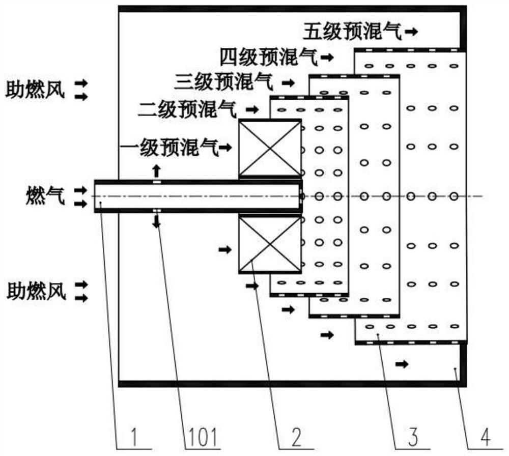
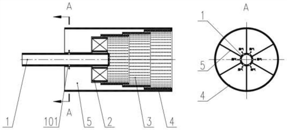
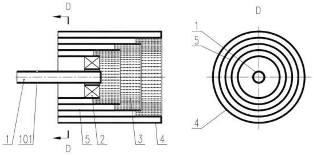
[0038] Such as figure 1 As shown, the parts involved in a step-by-step amplification method of a gas flame include an air gun 1, a stable combustion cover 2, an inner cylinder 3, an outer cylinder 4 and a premixing chamber partition 5, the inner cylinder 3 is divided into more than 3 levels, and the air gun 1 Several premix gas injection holes 101 are provided along the radial direction of the gun body.

[0039] Such as figure 1 As shown, 10-30% of the gas is directly sprayed into the interior of the inner barrel 3 at each level through the gun tip at the front end of the air gun 1. The flame formed by this part of the swirling gas is very stable, which can ensure that the main flame inside the inner cylinder will not be extinguished; 70-90% of the gas passes through several premixed gas radially arranged along the gun body of the air gun 1 The noz...


PUM


Abstract

The invention discloses a flame tube, an industrial low-nitrogen burner, and a gas flame step-by-step amplification method. The gas flame step-by-step amplification method is mainly embodied in the form of a flame tube, with stable flame and low NOx emission; high-speed smoke is ejected from the outlet of the flame tube. The flue gas in the injection furnace is recirculated to achieve low-nitrogen combustion with uniform temperature. In the absence of flue gas external circulation, the NOx emission can be controlled at 20 mg per standard square (3.5% O 2 )the following. The industrial low-nitrogen burner using the gas flame step-by-step amplification method, the flame tube is premixed combustion with an excess air coefficient greater than 1; the gas outside the flame tube is premixed and is ignited by the high-temperature flue gas ejected from the flame tube nozzle in the burner Combustion, the volume expansion of the ignited gas is accelerated and ejected from the burner outlet at high speed, and the flue gas in the ejector furnace is evenly mixed; the burner nozzle protrudes from the front wall of the furnace; part of the gas is injected into the leeward side of the burner to mix with the return flue gas Then it meets the burner nozzle flame to realize slow low-oxygen combustion.

Description

technical field [0001] The invention relates to the technical field of industrial low-nitrogen burners, in particular to a flame cylinder, an industrial low-nitrogen burner and a gas flame step-by-step method. Background technique [0002] The nitrogen oxides produced by gas burners are mainly thermal NOx, which is formed by oxidation of nitrogen in the air under high temperature conditions. The amount of nitrogen oxides produced mainly depends on the temperature and the time the flue gas stays in the high temperature area. Tests have shown that under the same conditions, the amount of NOx produced increases with the increase of temperature. When the temperature is lower than 1500 ° C, almost no thermal NOx is produced. Proportional to time. Therefore, considering the formation mechanism of thermal NOx, the combustion of gas burners should be properly organized to avoid the high temperature zone of combustion and shorten the residence time of flue gas in the high temperatur...

Claims


Application Information

Patent Timeline
Patent Type & Authority Patents(China)
IPC IPC(8): F23R3/28F23R3/52F23D14/02F23D14/46F23D14/62
CPCF23R3/286F23R3/52F23D14/02F23D14/46F23D14/62
Inventor 梁龙雍占锋李亮常春梅张举乐贾刚建邱康萍鲍村郭连法张红月廉旗任子康
Owner 徐州燃烧控制研究院有限公司
Why Eureka
Try Eureka