
Scanning method based on capacitive touch screen and capacitive touch screen

A technology of capacitive touch screen and scanning method, which is applied in the direction of electric digital data processing, instrument, data processing input/output process, etc., can solve the problems of unfavorable touch screen use experience, low touch point scanning efficiency, and large loss of touch screen, etc. Achieve the effect of shortening the scanning time, ensuring the scanning accuracy and high sensitivity

Pending Publication Date: 2021-02-09
HEBEI HUAFA EDUCATION TECH CORP LTD
View PDF0 Cites 0 Cited by
  • Summary
  • Abstract
  • Description
  • Claims
  • Application Information

AI Technical Summary

Problems solved by technology

[0004] The present invention provides a scanning method based on a capacitive touch screen and a capacitive touch screen, which can effectively solve the problem that the scanning of a touch point by a capacitive touch screen requires multiple global scans to determine the position in the above-mentioned background technology, which not only consumes less on the touch screen It is large, and the scanning time is long, and the scanning efficiency of the touch point is low, which is not conducive to improving the user experience of the touch screen.

Method used


Image

  • Scanning method based on capacitive touch screen and capacitive touch screen
  • Scanning method based on capacitive touch screen and capacitive touch screen
  • Scanning method based on capacitive touch screen and capacitive touch screen

Examples


Embodiment 1

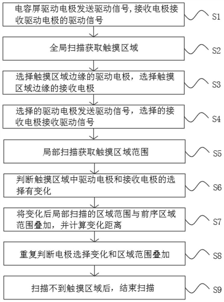
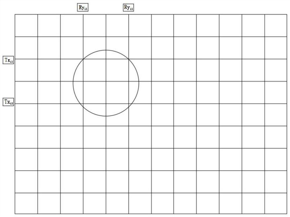
[0040] Such as figure 1 , 3 As shown in -4, the present invention provides a technical solution, a scanning method based on a capacitive touch screen, comprising the following scanning steps:

[0041] S1. The driving electrode of the capacitive screen sends the driving signal, and the receiving electrode receives the driving signal of the driving electrode;

[0042] S2, global scanning to obtain the touch area;

[0043] S3. Select the driving electrodes on the edge of the touch area, and select the receiving electrodes on the edge of the touch area;

[0044] S4. The selected driving electrode sends the driving signal, and the selected receiving electrode receives the driving signal;

[0045] S5. Partial scanning to obtain the range of the touch area;

[0046] S6, judging that the selection of the driving electrode and the receiving electrode in the touch area has changed;

[0047] S7. Superimpose the range of the touch area scanned locally after the change with the range ...

Embodiment 2

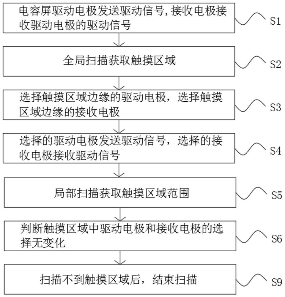
[0064] Such as Figure 2-3 As shown, the present invention provides a technical solution, a scanning method based on a capacitive touch screen, including the following scanning steps:

[0065] S1. The driving electrode of the capacitive screen sends the driving signal, and the receiving electrode receives the driving signal of the driving electrode;

[0066] S2, global scanning to obtain the touch area;

[0067] S3. Select the driving electrodes on the edge of the touch area, and select the receiving electrodes on the edge of the touch area;

[0068] S4. The selected driving electrode sends the driving signal, and the selected receiving electrode receives the driving signal;

[0069] S5. Partial scanning to obtain the range of the touch area;

[0070] S6, judging that there is no change in the selection of the driving electrode and the receiving electrode in the touch area;

[0071] S9. After the touch area cannot be scanned, the scanning ends.

[0072] According to the a...


PUM


Abstract

The invention discloses a scanning method based on a capacitive touch screen, which comprises the following scanning steps: S1, sending a driving signal by a capacitive screen driving electrode, and receiving the driving signal of the driving electrode by a receiving electrode; S2, globally scanning to obtain a touch area; S3, selecting the driving electrode at the edge of the touch area and the receiving electrode at the edge of the touch area; and S4, enabling the selected driving electrode to send a driving signal, and enabling the selected receiving electrode to receive the driving signal.According to the invention, by a global scanning and local scanning alternate scanning mode, the touch area is obtained through global scanning, the driving electrode at the edge of the touch area isselected to send the driving signal, and the driving signal is received through the receiving electrode; local scanning is carried out to determine the range of the touch area, and the local scanningarea is small, so that the scanning time is shortened, touch points can be conveniently and quickly scanned, the touch response speed is higher, the touch sensitivity is higher, and the use experience of the capacitive touch screen is improved.

Description

technical field [0001] The invention relates to the technical field of capacitive touch screens, in particular to a scanning method based on a capacitive touch screen and a capacitive touch screen. Background technique [0002] Capacitive touch screen technology uses the current induction of the human body to work. The capacitive touch screen is a four-layer composite glass screen. The inner surface and interlayer of the glass screen are each coated with a layer of ITO, and the outermost layer is a thin layer of silica glass protective layer. , the interlayer ITO coating is used as the working surface, and four electrodes are drawn from the four corners. The inner layer of ITO is the shielding layer to ensure a good working environment. When the finger touches the metal layer, due to the electric field of the human body, the user and the surface of the touch screen form a A coupling capacitor, the finger sucks a small current from the contact point, the current flows out fro...

Claims


Application Information

Patent Timeline
Patent Type & Authority Applications(China)
IPC IPC(8): G06F3/041G06F3/044
CPCG06F2203/04112G06F3/04166G06F3/0446
Inventor 蒋超武俊峰王鹏杨宏亮
Owner HEBEI HUAFA EDUCATION TECH CORP LTD
Learn More