
Electronic packaging device

An electronic packaging and encapsulation colloid technology, applied in circuits, electrical components, electrical solid devices, etc., can solve problems such as affecting the configuration of components in electronic devices and hindering the small size of electronic devices, saving manufacturing time, simplifying process methods, and reducing The effect of manufacturing cost

Pending Publication Date: 2021-02-09
CHIPMOS TECH INC
View PDF7 Cites 0 Cited by
  • Summary
  • Abstract
  • Description
  • Claims
  • Application Information

AI Technical Summary

Problems solved by technology

However, the design of configuring the smart card and the memory card separately will prevent the electronic device from achieving a small size, and will affect the configuration of components in the electronic device

Method used


Image

  • Electronic packaging device
  • Electronic packaging device
  • Electronic packaging device

Examples


Embodiment Construction

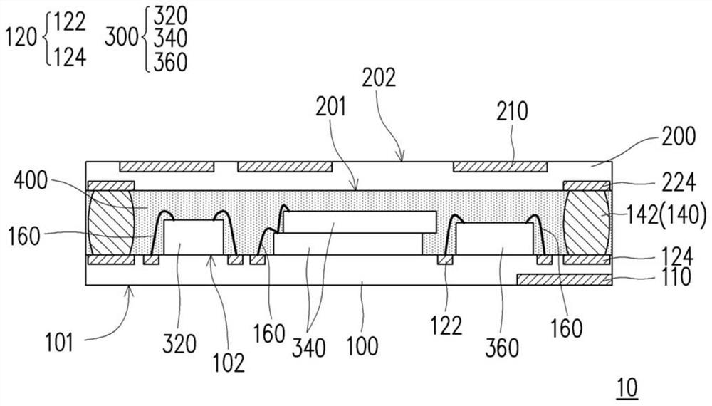
[0047] figure 1 is a schematic cross-sectional view of an electronic packaging device according to an embodiment of the present invention. Please refer to figure 1 , the electronic packaging device 10 includes a first carrier 100 , a second carrier 200 , a plurality of semiconductor elements 300 and an encapsulant 400 . In this embodiment, the second carrier 200 is arranged opposite to the first carrier 100 , and a plurality of semiconductor elements 300 are arranged on the first carrier 100 between the first carrier 100 and the second carrier 200 . The encapsulant 400 is disposed between the first carrier 100 and the second carrier 200 to cover the first carrier 100 , the second carrier 200 and the plurality of semiconductor elements 300 to complete the packaging of the electronic packaging device 10 . In this embodiment, the first carrier 100 and the second carrier 200 are, for example, circuit carriers capable of carrying semiconductor elements 300 (eg, chips), but the p...


PUM


Abstract

The invention provides an electronic packaging device. The electronic packaging device comprises a first carrier plate and a second carrier plate; a plurality of semiconductor elements arranged on oneof the first carrier plate and the second carrier plate, and packaging colloid arranged between the first carrier plate and the second carrier plate. The first carrier plate has a first surface and asecond surface opposite to the first surface. The first carrier plate includes at least one first external terminal disposed on the first surface. The second carrier plate is disposed opposite to thefirst carrier plate and has a third surface and a fourth surface opposite to the third surface. The second carrier plate includes at least one second external terminal disposed on the fourth surface.Third surface facing second surface. The encapsulant encapsulates the first carrier plate, the second carrier plate, and the plurality of semiconductor devices. The plurality of semiconductor elements respectively and electrically conduct the at least one first external terminal and the at least one second external terminal.

Description

technical field [0001] The invention relates to a packaging device, in particular to an electronic packaging device. Background technique [0002] With the change of payment habits of users, the integration of electronic wallets and prepaid stored value into portable electronic devices is one of the future development trends of electronic products. Generally speaking, the portable electronic device can use smart card (SmartCard) and memory card (Memory Card) respectively to achieve functions such as calculation, encryption, two-way communication, security function and data storage. [0003] Since portable electronic devices are constantly developing towards small size, multi-function and high performance, the internal space of the electronic devices is miniaturized. However, the design of configuring the smart card and the memory card separately will prevent the electronic device from achieving a small size, and will affect the configuration of components in the electronic ...

Claims


Application Information

Patent Timeline
Patent Type & Authority Applications(China)
IPC IPC(8): H01L25/065H01L23/31
CPCH01L25/0652H01L23/3114H01L23/3121H01L2224/48147H01L2224/48091H01L2924/181H01L2924/00014H01L2924/00012
Inventor 高靖尧王政杰
Owner CHIPMOS TECH INC
Learn More