
FM backscatter amplifier and backscatter system

A backscattering and amplifier technology, applied in the field of wireless communication, can solve the problems of high power consumption and short communication distance

Inactive Publication Date: 2021-02-09
XIDIAN UNIV
View PDF8 Cites 1 Cited by
  • Summary
  • Abstract
  • Description
  • Claims
  • Application Information

AI Technical Summary

Problems solved by technology

[0004] However, the existing FM backscatter tags only reflect the FM signal and load the required information, which consumes a lot of power and has a short communication distance

Method used


Image

  • FM backscatter amplifier and backscatter system
  • FM backscatter amplifier and backscatter system
  • FM backscatter amplifier and backscatter system

Examples


Embodiment 1

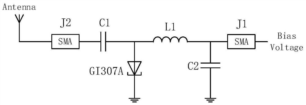
[0032] Because the traditional backscatter tags require a fixed source of radiation, which is not flexible enough and has a small coverage area, and the urban FM broadcast signal is a signal with a relatively wide coverage area and a relatively high transmission power in the city. Therefore, this embodiment uses the FM signal Design and fabricate the backscatter amplifier as the illumination source.

[0033] In general, FM signals can be represented as follows:

[0034]

[0035] Among them, s(t) is called the direct wave of the signal, f c is the carrier frequency, k f is the frequency sensitivity, is the phase message signal.

[0036] The modulation signal to FM can be regarded as multiplying the FM signal by cos(2πf b t), so the modulated FM signal is denoted as s b (t), called the reflected wave of the FM signal. which is:

[0037]

[0038] make Have

[0039]

[0040] Then s b (t) is the signal after the FM reflection, and is also the signal that actual...

Embodiment 2

[0068] On the basis of the first embodiment above, this embodiment provides an FM backscatter system, including a backscatter tag and a reader. The backscatter tag is used to receive the FM signal in the current area, and perform amplification and modulation Backscatter, the reader is used to receive the amplified and modulated signal, that is, the backscatter signal, and demodulate it to obtain the required information; wherein, the backscatter tag can be the one described in the first embodiment above FM backscatter amplifier. See Figure 7 , Figure 7 It is a schematic structural diagram of an FM backscattering system provided by an embodiment of the present invention.

[0069] Further, in this embodiment, in terms of reader reception, Gnuradio uses USRPB200 to receive and demodulate data, and the transmitted data can be successfully demodulated. See Figure 8 , Figure 8 is a schematic diagram of the working process of the system provided by the embodiment of the pres...


PUM


Abstract

The invention discloses an FM backscatter amplifier and a backscatter system, and the FM backscatter amplifier comprises a data receiving and transmitting module which is used for receiving an FM signal; the frequency selection module is connected with the data receiving and transmitting module and is used for carrying out frequency selection on the FM signal to obtain an FM signal with a certainfrequency band; the amplification module is connected with the frequency selection module and is used for amplifying the FM signal of the certain frequency band to obtain an amplified FM signal; and the modulation module is connected with the amplification module and is used for modulating the amplified FM signal and controlling the amplification module to reflect the amplified FM signal. According to the FM backscatter amplifier provided by the invention, the FM signal is amplified by utilizing the characteristics of the tunnel diode, and the reflected signal is increased under the conditionof ensuring very low power consumption, so that the purpose of prolonging the communication distance is achieved.

Description

technical field [0001] The invention belongs to the technical field of wireless communication, and in particular relates to an FM backscatter amplifier and a backscatter system. Background technique [0002] Backscatter technology is widely used due to its advantages of low power consumption and high flexibility. With the rise of the Internet of Things (IoT), backscattering technology plays an important role in the urban IoT. For example, the electronic toll collection system (ETC) is a relatively successful case of commercial application of backscatter technology. In future Internet of Things applications, backscattering technology still has a lot of application space. [0003] The traditional backscatter needs to provide an illumination source, which provides an illumination source by itself, sends it to the tag (TAG), and then the tag reflects and transmits the reflected signal to the reader (Reader). Because the traditional backscatter tags require a fixed irradiation...

Claims


Application Information

Patent Timeline
Patent Type & Authority Applications(China)
IPC IPC(8): H04B1/40H03F3/10
CPCH04B1/40H03F3/10
Inventor 马涛胡嘉
Owner XIDIAN UNIV
Learn More