Honeycomb plate processing equipment

A technology for processing equipment and honeycomb panels, applied in the directions of lamination device, lamination auxiliary operation, lamination, etc., can solve the problems of deviation, single-sided honeycomb panel breakage, and errors in front and rear traction mechanical processing, so as to improve production efficiency , Solve the drying problem, the drying effect is better

Pending Publication Date: 2021-02-12
应树丰
View PDF12 Cites 2 Cited by
  • Summary
  • Abstract
  • Description
  • Claims
  • Application Information

AI Technical Summary

Problems solved by technology

[0002] The honeycomb panel is composed of the first and second panels and the honeycomb core. In order to make the honeycomb panel dry quickly and the water content reach the standard, the honeycomb core is combined and dried separately from the first panel and the second panel, which greatly improves the drying efficiency. There are still some problems in the separation and compounding
Due to many external disturbances, such as different tension control between the first panel and the second panel, different sizes of reels, different loads, different front and rear traction forces, and errors in machining, etc., the linear speeds of the first panel and the second panel are different. , the single-sided honeycomb panel after the composite of the first panel and the honeycomb core cannot be synchronized with the second panel. Wrinkles, fractures, and uneven glue application. If the conveying speed of the single-sided honeycomb panel is slower than that of the second panel, the traction force during the second composite will break the single-sided honeycomb panel. Therefore, the speed difference between the front and rear will not only cause the single-sided honeycomb panel The one-sided honeycomb panel and the second panel are not firmly bonded, and the single-sided honeycomb panel will break, and it is impossible to achieve high-speed production of the honeycomb panel

Method used


Image

  • Honeycomb plate processing equipment
  • Honeycomb plate processing equipment
  • Honeycomb plate processing equipment

Examples


Embodiment Construction

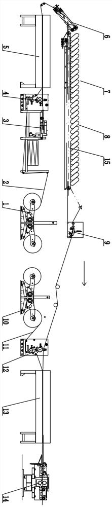
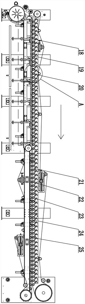
[0020] The details and working principles of the implementation modes and examples of the present invention will be described below with reference to the accompanying drawings. The processing equipment of this kind of honeycomb panel includes a single-sided forming mechanism and a double-sided forming mechanism, and a single-sided honeycomb panel storage station 7 is arranged between the single-sided forming mechanism and the double-sided forming mechanism. The mechanism and the double-sided forming mechanism work independently. The storage station is provided with a conveyor belt 15, and the conveying speed of the conveyor belt is slower than that of the single-sided forming mechanism. The single-sided forming mechanism includes a first panel frame 1. The honeycomb core pulling device 3, the first gluing device 4 and the first composite device 5, the first panel frame is provided with a material shaft, the first panel reel is arranged on the material shaft, and the double-side...


PUM


Abstract

The invention discloses honeycomb plate processing equipment which comprises a single-face forming mechanism and a double-face forming mechanism, a single-face honeycomb plate storage station is arranged between the single-face forming mechanism and the double-face forming mechanism, the single-face forming mechanism and the double-face forming mechanism operate independently, the storage stationis provided with a conveying belt, the conveying speed of the conveying belt is lower than the forming speed of the single-face forming mechanism, the single-face forming mechanism comprises a first panel frame, a honeycomb core pulling device, a first gluing device and a first compounding device, the double-face forming mechanism comprises a second panel frame, a second gluing device and a secondcompounding device, along the honeycomb core conveying direction, the storage station is arranged between the first compounding device and the second gluing device, gluing of the single-face honeycomb plate and compounding of the single-face honeycomb plate and a second panel are not affected by a single-face forming part, the single-face honeycomb plate and the second panel are firmly bonded, and high-speed production is achieved.

Description

technical field [0001] The invention relates to processing equipment for honeycomb panels. Background technique [0002] The honeycomb panel is composed of the first and second panels and the honeycomb core. In order to make the honeycomb panel dry quickly and the water content reach the standard, the honeycomb core is combined and dried separately from the first panel and the second panel, which greatly improves the drying efficiency. There are still some problems with separate compounding. Due to many external disturbances, such as different tension control between the first panel and the second panel, different sizes of reels, different loads, different front and rear traction forces, and errors in machining, etc., the linear speeds of the first panel and the second panel are different. , the single-sided honeycomb panel after the composite of the first panel and the honeycomb core cannot be synchronized with the second panel. Wrinkles, fractures, and uneven glue applic...

Claims


Application Information

Patent Timeline
IPC IPC(8): B32B37/12B32B37/10B32B37/00B32B38/18
CPCB32B37/1284B32B37/10B32B37/0046B32B38/1816B32B38/1841
Inventor 应树丰
Owner 应树丰
Why Eureka
Try Eureka