Neurological examination device
An inspection device and neurology technology, applied in the field of medical devices, can solve the problems of inconvenient adjustment of display screen height, poor practicality and applicability, troublesome use by different doctors, etc., to improve applicability and practicality, inspection effect and efficiency High, simple structure effect
- Summary
- Abstract
- Description
- Claims
- Application Information
AI Technical Summary
Problems solved by technology
Method used
Image
Examples
Embodiment 1
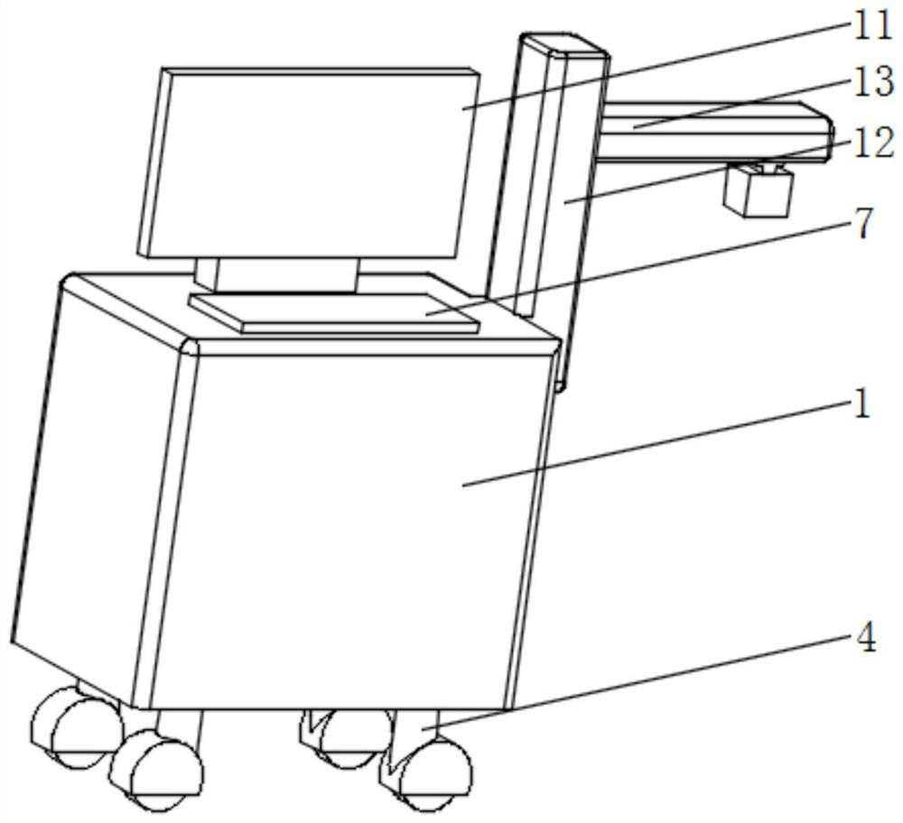
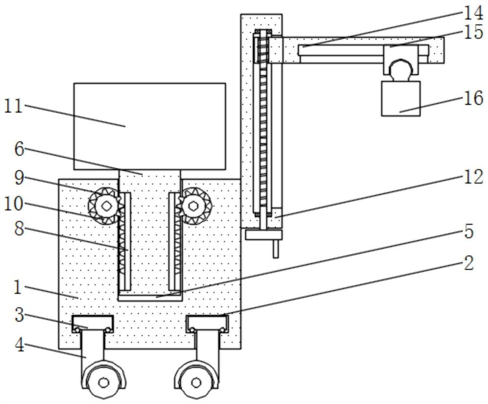
[0029] see Figure 1-4 , a neurology examination device, comprising a device body 1, the bottom of the device body 1 is symmetrically provided with a circular card slot 2, the inside of the circular card slot 2 is rotatably connected with a circular card block 3, and the bottom of the device body 1 is provided with Universal wheel 4 is arranged, and the top of universal wheel 4 stretches into circular draw-in groove 2 and is fixedly connected with the bottom middle part of circular block 3, and the rear side of the top middle part of device body 1 is provided with lifting chute 5, and lifting slide The inside of the groove 5 is slidingly connected with a lifting support plate 6, and the top of the lifting support plate 6 stretches out from the lifting chute 5 and is fixedly connected with a display screen 11. The front side of the top middle part of the device body 1 is fixedly connected with an operation panel 7, and the device body 1 The outer wall one side middle part top i...
Embodiment 2
[0032] see figure 2 and image 3 , the present embodiment has carried out further optimization on the basis of embodiment 1, specifically, there are four universal wheels 4, and the four universal wheels 4 are evenly and symmetrically distributed in a rectangular shape, and the four universal wheels 4 are connected to the four universal wheels respectively. Corresponding to two circular card slots.
[0033] Concretely, the top middle of both sides of the inner wall of the lifting chute 5 is symmetrically provided with transmission tooth grooves 9, and the rear side of the inner wall side of the lifting chute 5 close to the two transmission tooth grooves 9 communicates with the inside of the lifting chute 5. The middle parts of both sides of the outer wall of the support plate 6 are fixedly connected with lifting racks 8 .
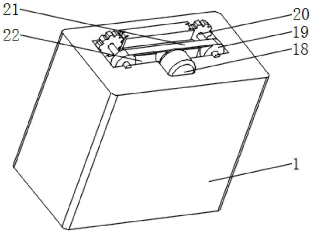
[0034] Specifically, the middle part of the inner wall rear side of the transmission tooth groove 9 is rotatably connected with a transmission shaft 20,...
Embodiment 3
[0038] see figure 2 and Figure 4 , the present embodiment is optimized as follows on the basis of example 1 or example 2, specifically, a T-shaped chute 14 is provided in the middle of the bottom end of the support horizontal plate 13, and a T-shaped chute 14 is slidingly connected inside the T-shaped chute. Sliding block 15, the bottom middle part of T-shaped sliding block 15 stretches out T-shaped chute 14 and is connected with the top middle part of inspection mechanism 16 in rotation.
[0039] Specifically, the height adjustment guide plate 12 is provided with a height adjustment chute 23 near the middle part of the outer wall side of the support horizontal plate 13, and the inside of the height adjustment chute 23 is slidably connected with a height adjustment slider 25, and one end of the height adjustment slider 25 stretches out. Elevate the chute 23 and be fixedly connected with the outer wall of the support horizontal plate 13.
[0040] Specifically, the top middl...
PUM
 Abstract
Description
Claims
Application Information
 - R&D
- Intellectual Property
- Life Sciences
- Materials
- Tech Scout
- Unparalleled Data Quality
- Higher Quality Content
- 60% Fewer Hallucinations
Browse by: Latest US Patents, China's latest patents, Technical Efficacy Thesaurus, Application Domain, Technology Topic, Popular Technical Reports.
© 2025 PatSnap. All rights reserved.Legal|Privacy policy|Modern Slavery Act Transparency Statement|Sitemap|About US| Contact US: help@patsnap.com


