Industrial waste gas high-concentration acid mist purification tower

An industrial waste gas and high-concentration technology, applied in chemical instruments and methods, separation of dispersed particles, use of liquid separation agents, etc., can solve problems such as inability to remove dust, low replacement efficiency, cumbersome operation, etc., to reduce labor intensity and automation High, good filtering effect

Active Publication Date: 2021-02-19
营口中润环境科技有限公司
View PDF11 Cites 1 Cited by
  • Summary
  • Abstract
  • Description
  • Claims
  • Application Information

AI Technical Summary

Problems solved by technology

[0004] In the process of realizing the present invention, the inventor found that at least the following problems in the prior art have not been solved: 1. The filter plate in the prior art is always above the absorption liquid, and the dust impurities in the exhaust gas are filtered by the filter plate to avoid dust impurities If the sprayer is blocked, the filter plate can be cleaned at any time. In view of the acid mist generated by electroplating production and processing pickling, the content of dust and impurities is relatively high. The existing technology uses a filter plate to filter, and the filtering effect is limited. The dust is better removed, and the filter plate needs to be replaced frequently. Since the filter plate is installed inside the tower body, the replacement of the filter plate needs to enter the tower body through the inspection port. The operation is cumbersome, the replacement efficiency is low, and the workers are laborious Higher strength; 2. In the prior art, after the acid gas enters the purification tower, it is directly sprayed and neutralized. At this time, the acid mist is not evenly distributed in the purification tower, resulting in insufficient contact between the acid mist and the slurry spray , thereby reducing the purification efficiency of acid mist

Method used


Image

  • Industrial waste gas high-concentration acid mist purification tower
  • Industrial waste gas high-concentration acid mist purification tower
  • Industrial waste gas high-concentration acid mist purification tower

Examples


Embodiment Construction

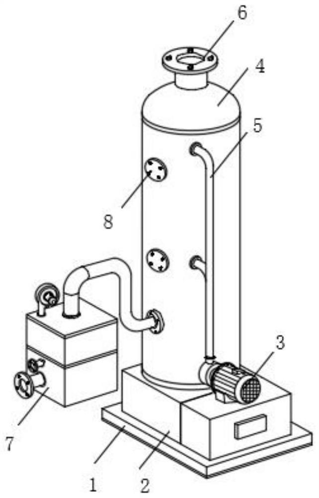
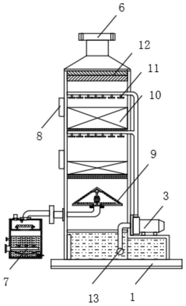
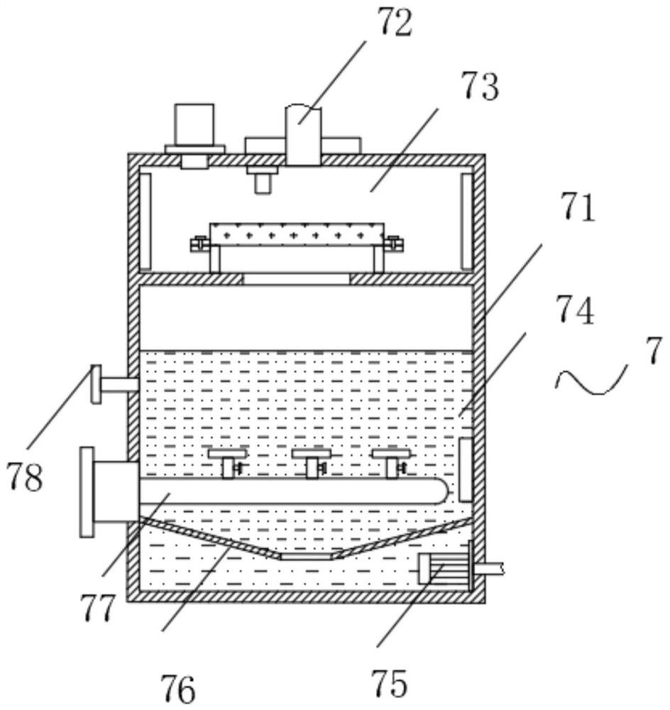
[0035] The following will clearly and completely describe the technical solutions in the embodiments of the present invention with reference to the accompanying drawings in the embodiments of the present invention. Obviously, the described embodiments are only some, not all, embodiments of the present invention. Based on the embodiments of the present invention, all other embodiments obtained by persons of ordinary skill in the art without making creative efforts belong to the protection scope of the present invention.

[0036] In describing the present invention, it is to be understood that the terms "center", "longitudinal", "transverse", "length", "width", "thickness", "upper", "lower", "front", " Back", "Left", "Right", "Straight", "Horizontal", "Top", "Bottom", "Inner", "Outer", "Clockwise", "Counterclockwise", etc. or The positional relationship is based on the orientation or positional relationship shown in the drawings, which is only for the convenience of describing t...


PUM


Abstract

The invention discloses an industrial waste gas high-concentration acid mist purification tower which comprises a base, and a working mechanism, a solid-phase separation mechanism and a gas homogenizing mechanism are arranged on the base; wherein the working mechanism comprises a liquid storage tank, a centrifugal water pump, a shell, a conveying pipeline, an air outlet, an observation hole, a packing layer, a spraying pipe, a demisting layer and a liquid suction pipe; the liquid storage tank is fixedly mounted on the upper surface of the base; and one end of the upper surface of the liquid storage tank is connected with the shell in a penetrating mode. The other end of the upper surface of the liquid storage tank is fixedly connected with the centrifugal water pump; a liquid suction pipeis fixedly connected to one end of the side surface of the centrifugal water pump, and one end of the liquid suction pipe penetrates through the shell and extends into the liquid storage tank. By arranging the solid-phase separation mechanism, the filtering effect is good, the automation degree is high, meanwhile, due to the fact that a filtering plate is not used, the filtering plate does not need to be frequently replaced and cleaned, and the labor intensity of workers is reduced.

Description

technical field [0001] The invention relates to the technical field of waste gas treatment, in particular to a high-concentration acid mist purification tower for industrial waste gas. Background technique [0002] With the increasing degree of industrialization, the resulting waste gas pollution has attracted more and more attention. These harmful gases must be strictly processed to meet the comprehensive atmospheric emission standards before they can be discharged into the atmosphere. At present, In the process of chemical processing, a large amount of acid mist gas is produced, polluting the air and affecting health. At present, acid mist purification towers are mainly used to treat acid mist gas, but the waste gas is often mixed with dust impurities, which are mixed into the absorption liquid. The absorption liquid is sprayed through the spray device, which is easy to block the spray device. If the filter plate is fixedly installed and the filter plate is installed below...

Claims


Application Information

Patent Timeline
Patent Type & Authority Applications(China)
IPC IPC(8): B01D53/40B01D53/80B01D53/96B01D53/18B01D47/02B01D53/26
CPCB01D53/40B01D53/80B01D53/96B01D53/18B01D53/1456B01D53/1425B01D47/021B01D53/26Y02A50/2351
Inventor 张全连孙洋洋
Owner 营口中润环境科技有限公司
Why Eureka
Try Eureka