Blanking device of reinforced backflow hollow-square-shaped HY fiber felt in flat heat pipe

A technology of flat heat pipes and fiber mats, applied in the direction of feeding devices, positioning devices, storage devices, etc., can solve the problems of low manual production efficiency and high labor intensity of workers, and achieve the goal of reducing the number of placements, reducing labor intensity, and facilitating recycling. Effect

Pending Publication Date: 2021-02-19
德清宏业晶体纤维有限公司
View PDF9 Cites 2 Cited by
  • Summary
  • Abstract
  • Description
  • Claims
  • Application Information

AI Technical Summary

Problems solved by technology

[0004] Aiming at the deficiencies of the prior art, the present invention provides a punching device for reinforced reflux-shaped HY fiber felt in a flat heat pipe, which solves the problems of low manual production efficiency and high labor intensity for workers

Method used


Image

  • Blanking device of reinforced backflow hollow-square-shaped HY fiber felt in flat heat pipe
  • Blanking device of reinforced backflow hollow-square-shaped HY fiber felt in flat heat pipe
  • Blanking device of reinforced backflow hollow-square-shaped HY fiber felt in flat heat pipe

Examples


Embodiment 1

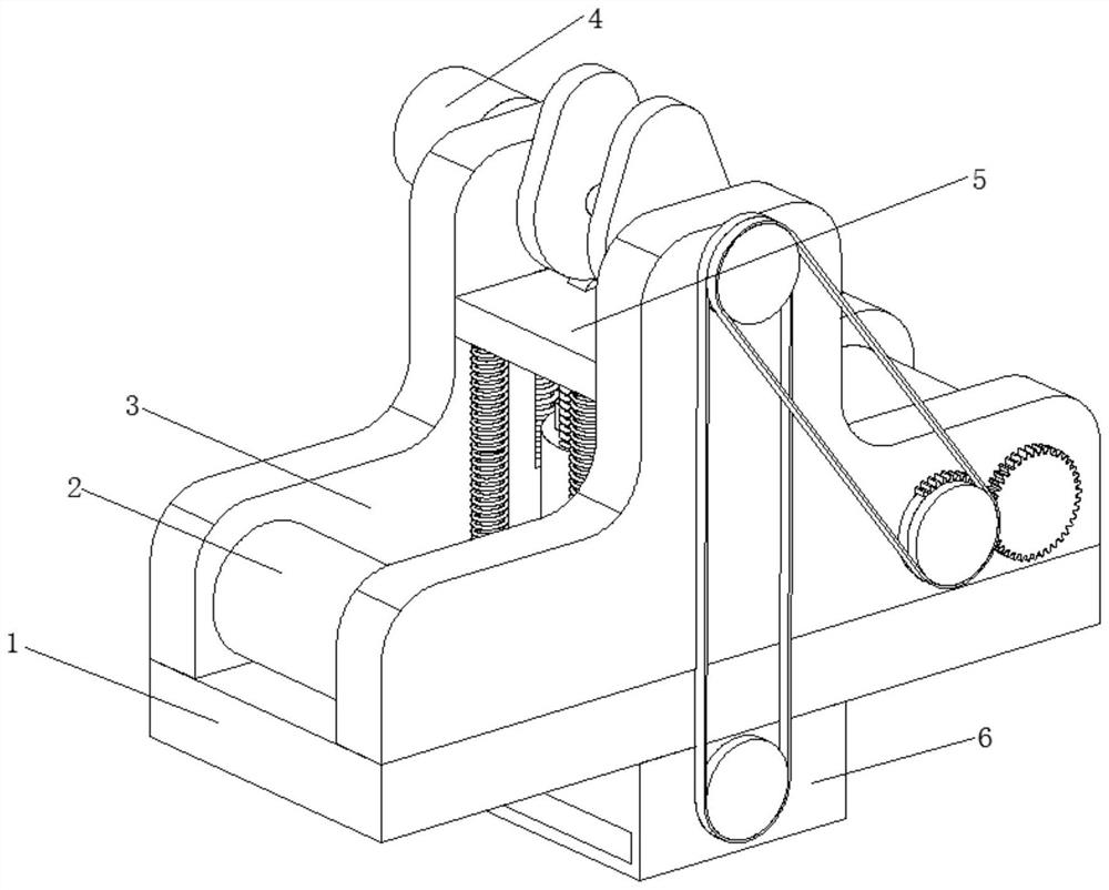
[0031] A kind of HY fiber mat punching device with enhanced reflow in the flat heat pipe, such as Figure 1-Figure 6 As shown, including a workbench 1, two side plates 3 are welded on the top of the workbench 1, a transmission mechanism 4 is arranged on the left side of the side plate 3, a punching mechanism 5 is arranged between the two side plates 3, and the workbench 1 The bottom of the bottom is provided with a collection mechanism 6, and the discharge roller 7 and the winding roller 8 are respectively rotated and connected between the two side plates 3, and the punching mechanism 5 is located between the discharge roller 7 and the winding roller 8, and the discharge roller 7 and the surfaces of the winding roller 8 are movably connected with the fiber felt body 2 .

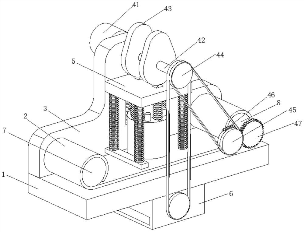
[0032] In this embodiment, the transmission mechanism 4 includes a motor 41, the output end of the motor 41 is welded with a rotating shaft 42, the surface of the rotating shaft 42 is clamped with two cams 43...

Embodiment 2

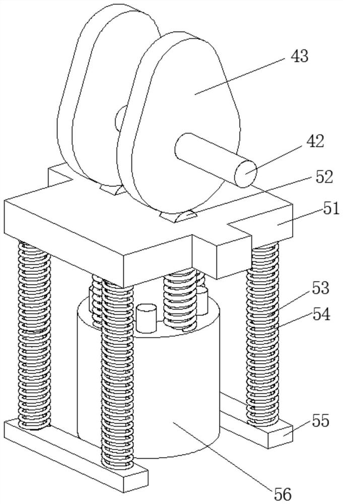
[0043] Such as Figure 6-Figure 7 As shown, on the basis of Embodiment 1, in this embodiment, the top ends of the inner column 561 and the connecting rod 563 are welded and fixed with the bottom of the fixed plate 51, and the two ends of the No. 4 spring 564 are respectively connected with the bottom of the fixed plate 51 and The tops of the jackets 562 are in contact with each other.

[0044] The outer jacket 562 and the inner column 561 can punch the fiber mat twice successively, which can realize the back shape of the fiber mat after punching, and successive punching can prevent the fiber mat from being cut when they are punched together, resulting in unqualified products There is no need for separate punching of the fiber mat twice, which can reduce the process and thus reduce the cost input.

[0045] It is worth noting that the collection mechanism 6 includes a collection box 61, the inner wall of the collection box 61 is rotatably connected with a connecting shaft 62, t...


PUM


Abstract

The invention relates to the technical field of fiber felt material post-treatment forming preparation, and discloses a blanking device of a reinforced backflow hollow-square-shaped HY fiber felt in aflat heat pipe. The blanking device comprises a workbench, two side plates are welded to the top of the workbench, a transmission mechanism is arranged at the left sides of the side plates, and a blanking mechanism is arranged between the two side plates; and a collecting mechanism is arranged at the bottom of the workbench, a discharging roller and a winding roller are rotationally connected between the two side plates correspondingly, and the surface of the discharging roller and the surface of the winding roller are both movably connected with a fiber felt body. According to the blanking device, the transmission mechanism and the blanking mechanism are used in a matched manner, so that the fiber felt can be directly and continuously blanked and automatically fed, manual cutting production by workers is not needed, the production efficiency can be greatly improved, and the labor intensity of the workers is reduced; and the collecting mechanism can be used for crushing and collectingleftover materials, the leftover materials can be conveniently recycled, and waste can be prevented.

Description

technical field [0001] The invention relates to the technical field of post-processing and forming preparation of fiber felt materials, in particular to a punching device for HY fiber felt with enhanced reflow in a flat heat pipe. Background technique [0002] With the continuous increase in the heat output of heat processors, many new technologies that contribute to radiators are also being developed. It is hoped that the selected materials will have high specific heat and high thermal conductivity at the same time. These two parameters of metal fiber felt are in the forefront. It has become a hot research direction in the current heat dissipation development. Metal fiber felt is a new type of porous material. It has a large specific surface area, low relative density, high cost performance, good heat transfer performance, and capillary performance. It is widely used in heat dissipation. The flat heat pipe enhanced reflux support column is under production. [0003] At pre...

Claims


Application Information

Patent Timeline
Patent Type & Authority Applications(China)
IPC IPC(8): B21D28/20B21D28/04B21D43/08B21D43/20B02C18/14B02C18/24
CPCB21D28/20B21D28/04B21D43/08B21D43/20B02C18/14B02C18/24
Inventor 戴江平
Owner 德清宏业晶体纤维有限公司
Why Eureka
Try Eureka