Method and device for feeding and discharging polymer tubes and bars

A technology of polymer tubes, material in and out, applied in the direction of transportation and packaging, metal processing, conveyor objects, etc., can solve problems such as safety hazards, low work efficiency, error-prone, etc., to ensure safety, improve efficiency, and ensure processing quality effect

Inactive Publication Date: 2021-02-19
ZHUZHOU HONGDA POLYMER MATERIALS
View PDF8 Cites 1 Cited by
  • Summary
  • Abstract
  • Description
  • Claims
  • Application Information

AI Technical Summary

Problems solved by technology

When placing and taking away tubes, rods, and switchgear, the staff need to walk around the machine tool to complete it. Not only is the work efficiency low, but the staff is easily fatigued in this monotonous and repetitive working state, and there is a big problem. security risks
[0005] 2. When the pipe is long, a special positioning device needs to be made, and only one end can be processed at a time, which is inefficient. It is also easy to make the outer surface of the pipe and rod in the locking mechanism when the pipe and rod are put into the manual locking mechanism. Scratches occur on the parts, making the tube and rod a defective product
[0006] 3. When processing multiple long polymer tubes and rods, it usually needs to use multiple processes for processing, and the switching of each process depends on manual switching. Manual switching has low work efficiency, error-prone, and potential safety hazards, etc. Defects, when the polymer tube rod is clamped and fed, the surface is easily scratched, resulting in unstable quality and high scrap rate
Specifically, the above-mentioned patents do not disclose the use of a clamping mechanism to clamp the pipe and rod at the feeding place, and move it to the product processing mechanism, and use the product processing mechanism to process the pipe and rod

Method used


Image

  • Method and device for feeding and discharging polymer tubes and bars
  • Method and device for feeding and discharging polymer tubes and bars
  • Method and device for feeding and discharging polymer tubes and bars

Examples


Embodiment 1

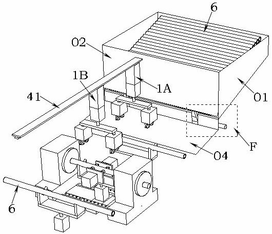
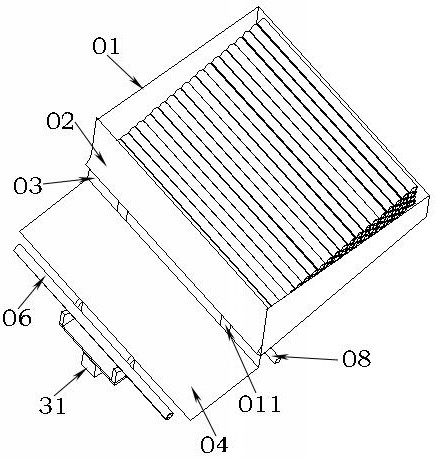
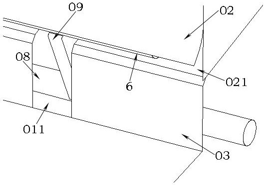
[0039] Such as figure 1 , figure 2 , image 3 and Figure 4 As shown, the automatic feeding mechanism includes a box body, a curling door, a receiving plate, a transmission plate and a pushing mechanism. The bottom of the box body is an inclined plane, and multiple pipes and rods to be processed are neatly placed in the box body. The rear end of the box body is provided with a rolling door, the lower end of the rolling door is rolled up, and a transmission hole is opened between the lower end of the rolling door and the bottom of the box body. When the tube and bar closest to the transmission hole in the casing were not jacked up, the tube and bar could roll out from the transmission hole. In order to allow the tubes and rods in the box to roll out one by one at regular intervals, a plate hole is opened at the bottom of the box and a pushing mechanism is arranged below the box. The upper surface of the transmission plate is also an inclined slope, the upper end of the rec...


PUM


Abstract

The invention relates to a method and a device for feeding, discharging and mounting polymer tubes and bars. According to the method, an automatic feeding mechanism is used for conveying the tubes andbars to a supporting mechanism, a first clamping mechanism is used for clamping the tubes and bars on the supporting mechanism at the feeding position, the tubes and bars are moved to a product machining mechanism, and the product machining mechanism machines the tubes and bars; after the tubes and bars are machined, the first clamping mechanism is used for clamping the tubes and bars again, thetubes and bars are moved to a supporting mechanism at the discharging position, meanwhile a second clamping mechanism is used for clamping the tubes and bars on the supporting mechanism at the feedingposition, and the tubes and bars are moved to the product machining mechanism; and finally, the first clamping mechanism and the second clamping mechanism retreat together until the first clamping mechanism moves to the position above the supporting mechanism at the feeding position, and resetting of the first clamping mechanism and the second clamping mechanism is completed. By means of the method and the device, the machining efficiency of the polymer tubes and bars can be improved, the machining quality of products in the machining process is ensured, and safe machining is guaranteed.

Description

technical field [0001] The invention relates to the field of machining of polymer tubes and rods, in particular to an automatic method and device for feeding and discharging materials during the processing of polymer tubes and rods. Background technique [0002] At present, because of the long length of polymer tubes and rods, when the two ends are processed separately through the limit, the tubes and rods must be turned around during the processing process, and the control of the processing process is all done manually, which has low efficiency, high cost, and unstable processing quality. The material of the long tube rod is relatively soft and easy to shake, so it is difficult to process both ends at the same time. The processing of long polymer tube rods realizes automatic loading and unloading, because the material is long, and the surface of the polymer material is very easy to scratch during the feeding process, so it is very difficult to realize automatic intelligent ...

Claims


Application Information

Patent Timeline
Patent Type & Authority Applications(China)
IPC IPC(8): B26D7/01B26D7/02B26D7/06B26D7/00B26D5/02B65G47/91
CPCB26D5/02B26D7/01B26D7/02B26D7/0608B26D7/0641B26D2007/0012B26D2007/013B65G47/912
Inventor 曾维楚邓平刘广张立群曾伟宋正科
Owner ZHUZHOU HONGDA POLYMER MATERIALS
Why Eureka
Try Eureka