Friction type mechanical continuously variable transmission

A continuously variable transmission, friction-type technology, applied in the direction of mechanical equipment, friction transmission devices, transmission device parts, etc., can solve the problems of fatigue damage surface, peeling, surface wear of components, etc., to achieve high transmission efficiency, low noise and long life Effect

Pending Publication Date: 2021-02-19
YULIN UNIV
View PDF0 Cites 0 Cited by
  • Summary
  • Abstract
  • Description
  • Claims
  • Application Information

AI Technical Summary

Problems solved by technology

The sliding state will generate heat. If the lubricating oil film is unevenly distributed or the thickness is not enough, the surface of the components will be worn or glued. After a long time, fatigue damage or surface peeling will occur, which will affect the normal operation of the transmission and reduce the transmission efficiency of the transmission.

Method used


Image

  • Friction type mechanical continuously variable transmission
  • Friction type mechanical continuously variable transmission

Examples


Embodiment Construction

[0010] In order to make the object, technical solution and advantages of the present invention clearer, the present invention will be further described in detail below in conjunction with the accompanying drawings and embodiments. It should be understood that the specific embodiments described here are only used to explain the present invention, not to limit the present invention.

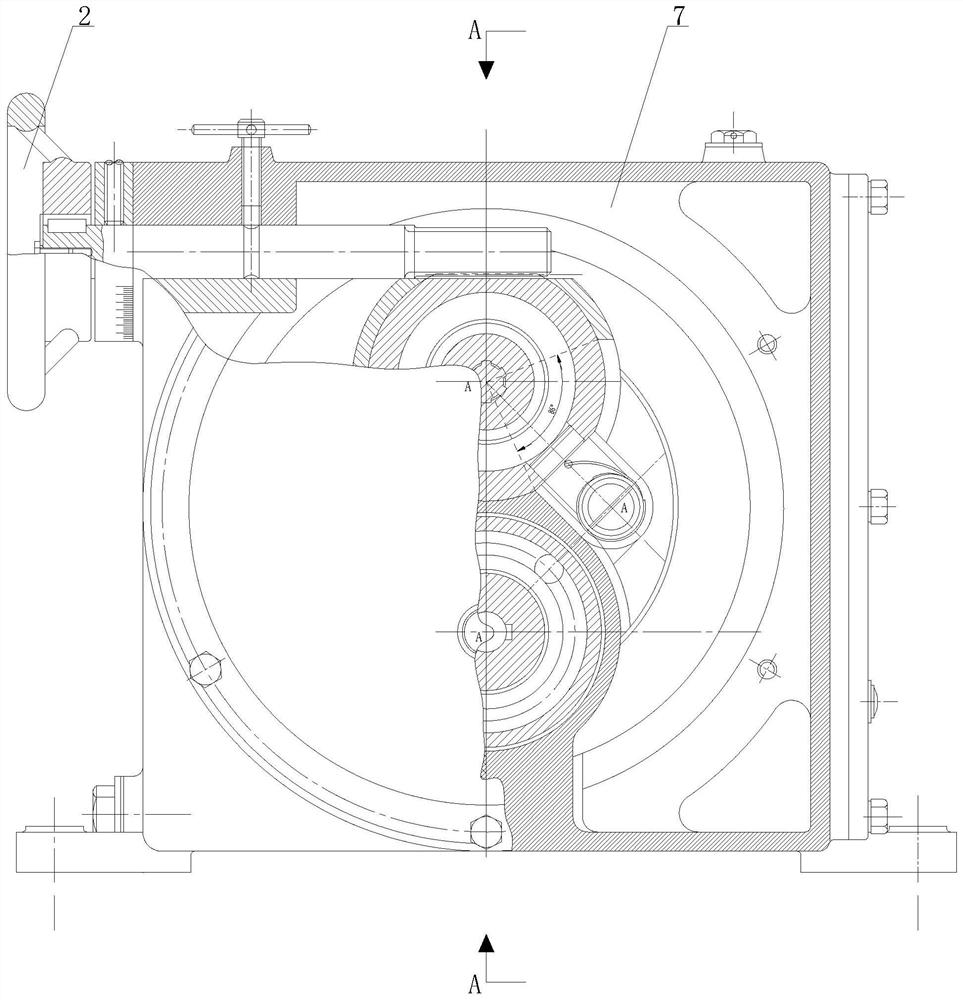
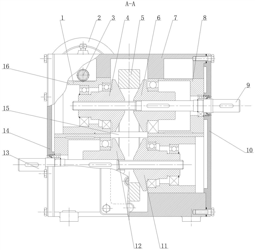
[0011] Such as Figure 1-2 As shown, the friction mechanical continuously variable transmission of this embodiment consists of an adjusting sleeve 1, a hand wheel 2, a gear 3, a left driving bevel wheel 4, a steel ring 5, a right driving bevel wheel 6, a box body 7, a sleeve 8, a driving Axle 9, right end cover 10, right driven cone wheel 11, left driven cone wheel 12, driven shaft 13, left end cover 14, pull rod 15, adjustment sleeve 16 are connected to form.

[0012] A left end cover 14 is installed at the left end of the casing 7, and a right end cover 10 is installed at the right end of the ca...


PUM


Abstract

The invention discloses a friction type mechanical continuously variable transmission. A left end cover is arranged at the left end of a box body; a right end cover is arranged at the right end of thebox body; a driving shaft is arranged in the box body; a left driving cone pulley and a right driving cone pulley are arranged on the outer side of the circumference of the driving shaft; a steel ring is arranged between the left driving cone pulley and the right driving cone pulley; an adjusting sleeve meshed with the gear is arranged on the outer side of the left driving cone pulley in the boxbody and connected with a pull rod; a driven shaft is arranged in the box body; a left driven cone pulley and a right driven cone pulley are arranged on the outer side of the circumference of the driven shaft; and a steel ring is arranged between the left driven cone pulley and the right driven cone pulley. According to the friction type mechanical continuously variable transmission provided by the invention, power of the driving shaft is transmitted to the left driven cone pulley and the right driven cone pulley through friction forces between the steel ring and the left driving cone pulley as well as between the steel ring and the right driving cone pulley, the friction forces between the steel ring and the left driving cone pulley as well as between the steel ring and the right drivingcone pulley are transmitted to the driven shaft, so that constant-power output can be achieved. The friction type mechanical continuously variable transmission has the advantages that the transmissionefficiency is high, the service life is long, the noise is low, and the vibration is small.

Description

technical field [0001] The invention belongs to the technical field of mechanical transmission continuously variable transmission, and in particular relates to a friction type mechanical continuously variable transmission. Background technique [0002] The friction continuously variable transmission relies on the friction force between the transmission parts to transmit torque, and adjusts the transmission ratio by changing the transmission ratio radius between the transmission parts. The friction continuously variable transmission generally includes a pressing device and a power transmission device. The pressing device is to form a sufficient pressing force between the elements in contact with each other, thereby forming sufficient frictional force to transmit power. The contact point pressure of transmission elements is very high, relying on friction or oil film traction, there will always be mutual sliding. The sliding state will generate heat. If the lubricating oil fil...

Claims


Application Information

Patent Timeline
IPC IPC(8): F16H15/42F16H57/023F16H57/029F16H57/031F16H57/028F16H61/664
CPCF16H15/42F16H57/023F16H57/029F16H57/031F16H57/028F16H61/664
Inventor 罗迎曹金玲
Owner YULIN UNIV
Why Eureka
Try Eureka