An integrated circuit packaging structure

A packaging structure, integrated circuit technology, applied in the direction of circuits, electrical components, electrical solid devices, etc., can solve the problems of reduced efficiency of chip replacement or maintenance, increased work intensity of staff, and inconvenient installation of packaging structures, etc., to improve the scope of application , reduced strength, easy installation

Active Publication Date: 2021-11-02
JIANGSU YOURUN MICROELECTRONICS CO LTD
View PDF7 Cites 1 Cited by
  • Summary
  • Abstract
  • Description
  • Claims
  • Application Information

AI Technical Summary

Problems solved by technology

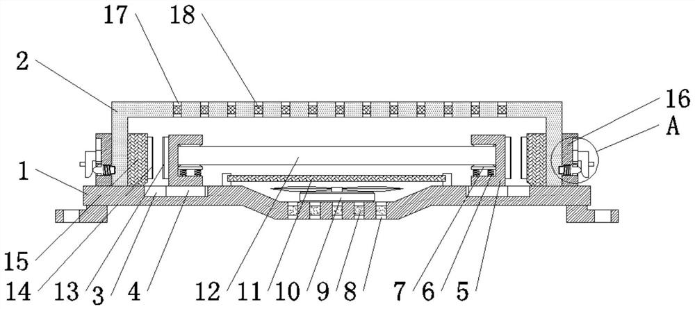
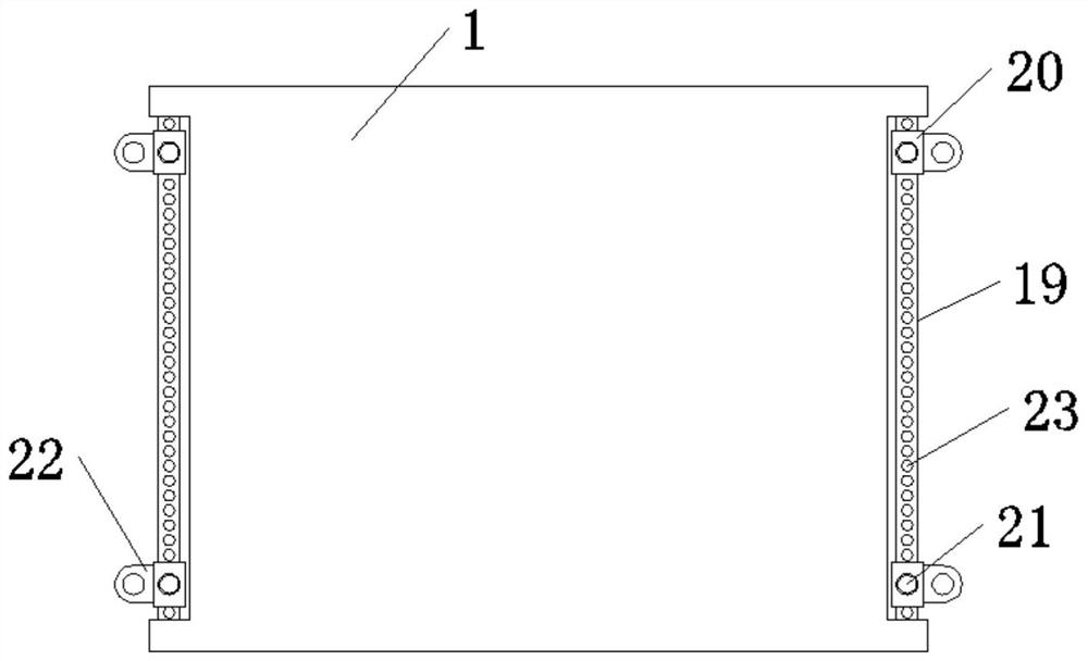
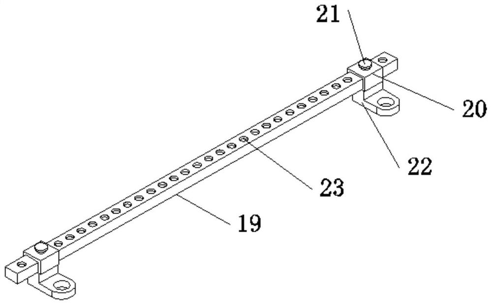
[0004] The purpose of the present invention is: in order to solve the problem that most of the current integrated circuits fix the chip directly in the tube shell when the chip needs to be replaced or overhauled, it takes a long time to disassemble the bolt to take out the chip, which not only increases It increases the working intensity of the staff, and at the same time, it will lead to a decrease in the efficiency of chip replacement or maintenance. At the same time, the structure of the packaging structure is single, which is not convenient for packaging chips of different lengths and widths. The scope of application is small, and the distance between the mounting parts is fixed. , when installing, the mounting holes on the device do not necessarily correspond to the mounting parts, so that the installation of the packaging structure is very inconvenient, and an integrated circuit packaging structure is provided

Method used


Image

  • An integrated circuit packaging structure
  • An integrated circuit packaging structure
  • An integrated circuit packaging structure

Examples


Embodiment Construction

[0024] The following will clearly and completely describe the technical solutions in the embodiments of the present invention with reference to the accompanying drawings in the embodiments of the present invention. Obviously, the described embodiments are only some of the embodiments of the present invention, not all of them. Based on the embodiments of the present invention, all other embodiments obtained by persons of ordinary skill in the art without making creative efforts belong to the protection scope of the present invention.

[0025] In the description of the present invention, it should be noted that the terms "center", "upper", "lower", "left", "right", "vertical", "horizontal", "inner", "outer" etc. The indicated orientation or positional relationship is based on the orientation or positional relationship shown in the drawings, and is only for the convenience of describing the present invention and simplifying the description, rather than indicating or implying that ...


PUM


Abstract

The invention discloses an integrated circuit packaging structure, which relates to the field of integrated circuit packaging. The invention includes a mounting plate. A connecting plate, a fixing plate and a first chute are fixed on both sides of the top of the mounting plate. The inside of the first chute passes through The first slider is connected with a clamping piece, a top plate is connected under the inner side of the clamping piece through a first spring, and a chip is arranged on the top of the top plate. When maintenance is required, the staff moves the pressing piece upward through the toggle block, and the pressing piece moves upward in the second chute through the second sliding block, so that the pressing piece does not limit the limit rod, and the second sliding block moves upward in the second chute. Under the reset action of the spring, the limit rod and the limit groove are separated, so that the staff can separate the protective shell from the installation plate, which makes the disassembly easier, the maintenance is more convenient, and the strength of the staff is reduced.

Description

technical field [0001] The invention relates to the technical field of integrated circuits, in particular to an integrated circuit packaging structure. Background technique [0002] An integrated circuit is a microelectronic device or component that uses a certain process to interconnect components such as transistors, resistors, capacitors, and inductors required in a circuit, and interconnects them together to form a small or several small semiconductor chips or chips. Dielectric substrate, and then encapsulated in a package, to become a microstructure with the required circuit function, in which all components have been structurally integrated, making electronic components towards miniaturization, low power consumption, intelligence and high reliability. A big step forward in terms of sex. The position of the integrated circuit package in the electronic pyramid is both the apex and the base of the pyramid. There are sufficient grounds for saying that it is in both positi...

Claims


Application Information

Patent Timeline
Patent Type & Authority Patents(China)
IPC IPC(8): H01L23/04H01L23/10H01L23/32H01L23/36H01L23/467
CPCH01L23/04H01L23/10H01L23/32H01L23/36H01L23/467
Inventor 谭美龙
Owner JIANGSU YOURUN MICROELECTRONICS CO LTD
Why Eureka
Try Eureka