High-speed intelligent band sawing machine

An intelligent band sawing machine, high-speed technology, applied in the field of sawing machines, can solve the problems of inability to form a closed loop, few feed speed adjustment parameters, and inability to adjust the sawing speed in time, so as to achieve the effect of ensuring the sawing effect and the life of the sawing belt.

Active Publication Date: 2021-02-23
浙江锯力煌工业科技股份有限公司 +1
View PDF9 Cites 2 Cited by
  • Summary
  • Abstract
  • Description
  • Claims
  • Application Information

AI Technical Summary

Problems solved by technology

[0005] The present invention aims to overcome the problems that the control system of the band sawing machine in the prior art cannot form a closed loop, the sawing speed cannot be adjusted in time, the adjustment parameters of the feed speed are too few, and the life of the saw band canno

Method used


Image

  • High-speed intelligent band sawing machine
  • High-speed intelligent band sawing machine
  • High-speed intelligent band sawing machine

Examples


Embodiment 1

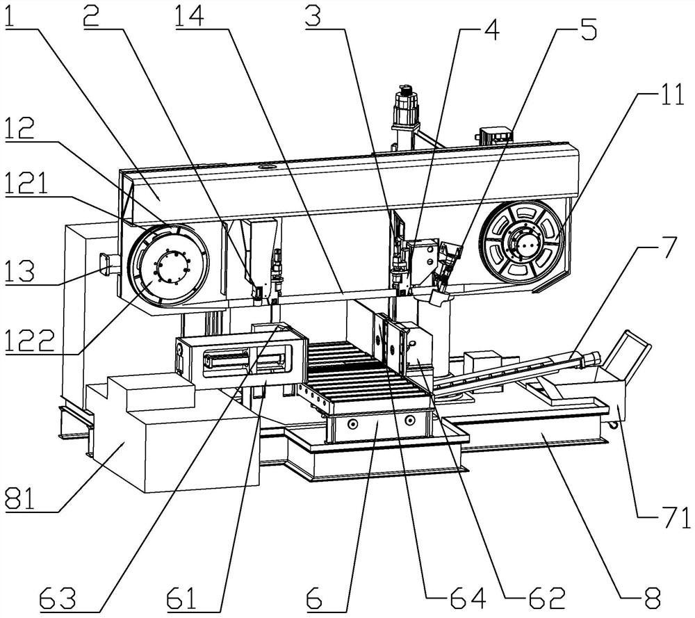
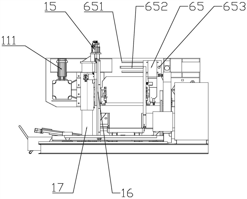
[0046] Such as figure 1 , figure 2 In the shown embodiment 1, a high-speed intelligent band sawing machine includes a base, a bed platform and a saw frame 1, the bed platform is arranged on the base, and is used to place and clamp transport materials, and the bed platform includes a feeding belt 6, respectively The front clamping device and the rear clamping device on the front side and the rear side of the saw band, the rear clamping device is slidably arranged on the bed platform along the feeding direction, and the front clamping device includes a front movable jaw 63 and a front movable jaw on both sides of the feeding belt. The front micro-movement jaw 64, the rear clamping device includes a rear movable jaw 61 and a rear micro-movement jaw 62 on both sides of the feeding belt, the rear movable jaw 61 and the rear micro-motion jaw 62 are connected at the bottom, and the front movable jaw 63 and the rear movable jaw 61 are slidably connected on the bed platform along the...

Embodiment 2

[0059] Such as Figure 8 In the shown embodiment 2, a high-speed intelligent band sawing machine has roughly the same structure as that of embodiment 1, the difference is that the lowest points of the two adjacent circular arc concave surfaces 323 are connected by a concave plane, A long concave surface 324 with both ends being circular arc surfaces is formed, and the long concave surface 324 extends along the circumferential direction.

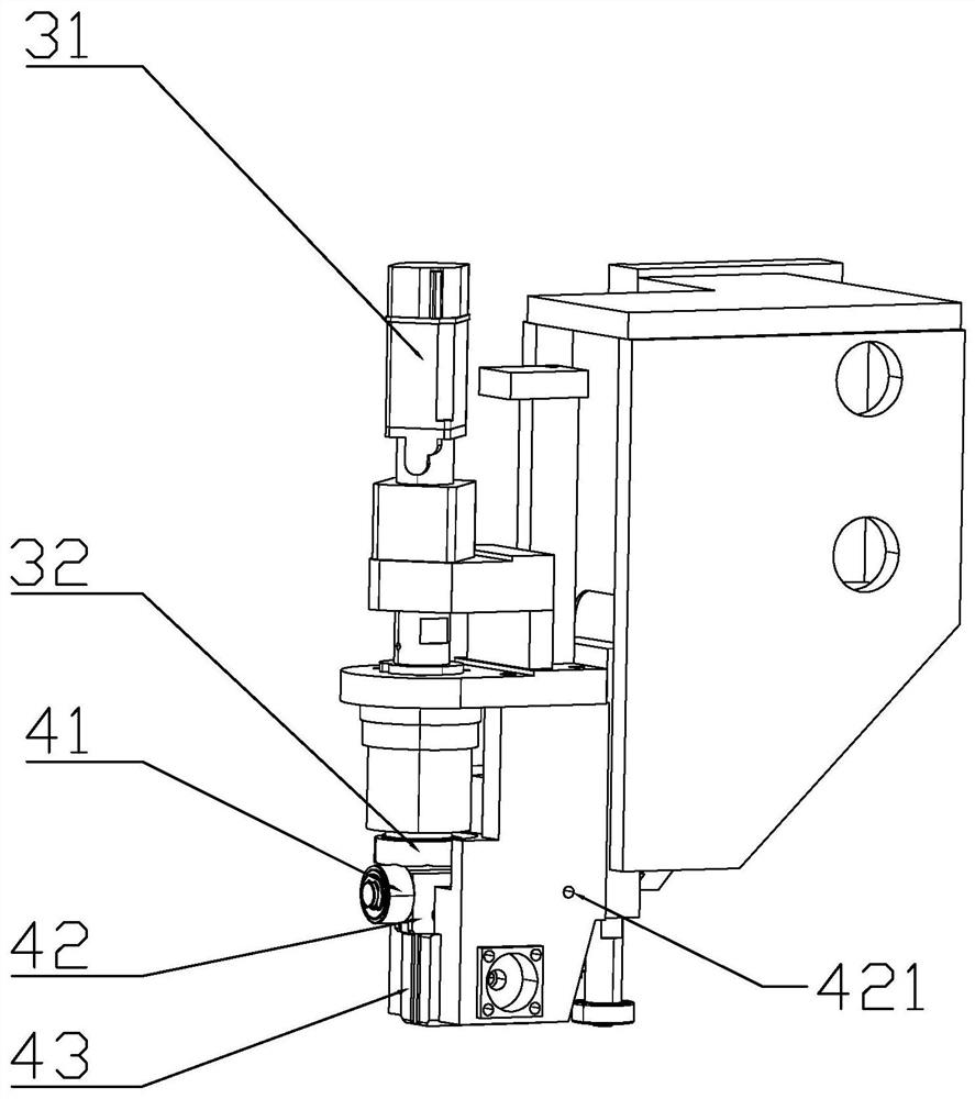
[0060] After the pulse chip breaking device is started, the toggling surface drives the pulse bearing 41 to rotate. When the circular arc concave surface 323 of the toggling surface contacts the bearing, the end of the point pressing member 42 vibrates up and down at a certain frequency at the same time, pressing The back of the saw band makes the saw band vibrate up and down according to the frequency; when the long concave surface 324 of the toggle surface is rotated to contact with the bearing, the contact time between the long concave sur...

Embodiment 3

[0062] A high-speed intelligent band sawing machine, the structure of which is roughly the same as that of Embodiment 2, the difference is that an outwardly convex arc convex surface is provided between the arc concave surfaces 323, and the toggle surface extends circumferentially except for the long concave surface 324 wavy surface. When the bearing abuts against the wave surface, the saw band performs simple harmonic vibration, which increases the downward pressure range and enhances the chip breaking effect.


PUM


Abstract

The invention discloses a high-speed intelligent band sawing machine. The high-speed intelligent band sawing machine comprises a bed table, a saw frame, a tensioning detection device, a saw back pressure feedback device and a servo lifting driving system, wherein the bed table is used for containing, clamping and transporting materials. the saw frame is arranged above the bed table, the saw frameis rotatably connected with a driving wheel and a driven wheel which are driven by a main servo motor, and the driving wheel and the driven wheel are sleeved with a saw band; the tensioning detectiondevice is used for detecting and adjusting the tensioning force of the saw band; the saw back pressure feedback device is used for detecting the back pressure of the saw band; and the servo lifting driving system controls the lifting speed of the saw frame according to the back pressure of the saw band and the feedback value of the output torque of the main servo motor, and controls the rotating speed of the main servo motor according to the feedback value of the lifting speed of the saw frame. According to the high-speed intelligent band sawing machine, the feeding speed is controlled throughdouble feedback, the sawing speed is adjusted through the feeding speed, closed-loop vector control is formed, the sawing efficiency is optimized, and the service life of the saw band is prolonged.

Description

technical field [0001] The invention relates to the technical field of sawing machines, in particular to a high-speed intelligent band sawing machine. Background technique [0002] A band sawing machine generally includes a base, a bed and a saw frame. A bed is installed on the base. The saw belt is set on the driving wheel and the driven wheel by tension. Only when the saw belt has enough tension can it move with the driving wheel and drive the driven wheel to rotate. However, when the tension is too large , the life of the saw band will be affected, so the tension needs to be adjusted in time; the rotation of the driving wheel drives the circular movement of the saw band. While moving vertically downward (that is, in the feed direction), only when the sawing speed and feed rate are reasonably configured can the sawing efficiency and the service life of the saw band be optimized; on the other hand, due to the material Parameters such as the material, shape and hardness of...

Claims


Application Information

Patent Timeline
IPC IPC(8): B23D55/00B23D55/04B23D59/00
CPCB23D55/00B23D55/04B23D59/00Y02P70/10
Inventor 李斌胜王定胜杜敏鹏卢勇波应晓伟胡德亮宋勇波陈杰斌李辉陈瑞雷梅联超
Owner 浙江锯力煌工业科技股份有限公司
Why Eureka
Try Eureka