Sintering furnace for silicon nitride ceramic sintering and working method of sintering furnace

A silicon nitride ceramics and sintering furnace technology, applied in the field of sintering furnaces, can solve problems such as inability to ensure uniformity of sintering temperature, product hardness, adverse effects on strength, uneven heating temperature, etc., so as to improve sintering efficiency and reduce the impact , The effect of continuous and uniform heating temperature

Active Publication Date: 2021-02-23
宁波银瓷新材料有限公司
View PDF11 Cites 0 Cited by
  • Summary
  • Abstract
  • Description
  • Claims
  • Application Information

AI Technical Summary

Problems solved by technology

[0003] The above schemes have the following disadvantages: 1) The uniformity of the sintering temperature cannot be ensured; 2) The non-uniform heating temperature may lead to recrystallization of the sintered alloy material, which will have an adverse effect on the hardness and strength of subsequent products.

Method used


Image

  • Sintering furnace for silicon nitride ceramic sintering and working method of sintering furnace
  • Sintering furnace for silicon nitride ceramic sintering and working method of sintering furnace
  • Sintering furnace for silicon nitride ceramic sintering and working method of sintering furnace

Examples


Embodiment 1

[0057] When the high-pressure gas passed into the pipeline device 4 does not reach the heating temperature;

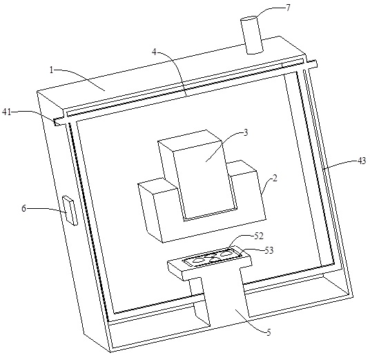
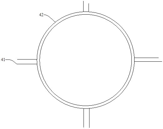
[0058] Such as Figure 1~8 As shown, a sintering furnace for sintering silicon nitride ceramics is provided. The sintering furnace includes a furnace body 1 and a heating element 2. The heating element 2 is arranged inside the furnace body 1. The heating element 2 is an electric heating element, such as a carbon rod, a carbon tube The heating element 2 is fixedly connected in the furnace body 1 through a support frame, and the crucible 3 carried on the heating element 2 is arranged on the heating element 2 for heating. The sintering furnace for sintering silicon nitride ceramics also includes a A pipeline device 4 for transmitting high-pressure gas, wherein the pipeline device 4 is suitable for transmitting the high-pressure gas that has not reached the heating temperature to the lower part of the heating element 2 . The high-pressure gas that does not reach the heati...

Embodiment 2

[0064] When the high-pressure gas passed into the pipeline device 4 reaches the heating temperature;

[0065] Such as Figure 1~7 and Figure 9 As shown, a sintering furnace for sintering silicon nitride ceramics is provided. The sintering furnace includes a furnace body 1 and a heating element 2. The heating element 2 is arranged inside the furnace body 1. The heating element 2 is an electric heating element, such as a carbon rod, a carbon tube The heating element 2 is fixedly connected in the furnace body 1 through a support frame, and the crucible 3 carried on the heating element 2 is arranged on the heating element 2 for heating. The sintering furnace for sintering silicon nitride ceramics also includes a The pipeline device 4 for transmitting high-pressure gas, wherein the pipeline device 4 is suitable for transmitting the high-pressure gas to the lower part of the heating element 2 . The high-pressure gas is injected into the furnace body 1 through the pipeline device ...

Embodiment 3

[0078] The third embodiment is carried out on the basis of the above embodiments.

[0079] This embodiment provides a working method of a sintering furnace for sintering silicon nitride ceramics.

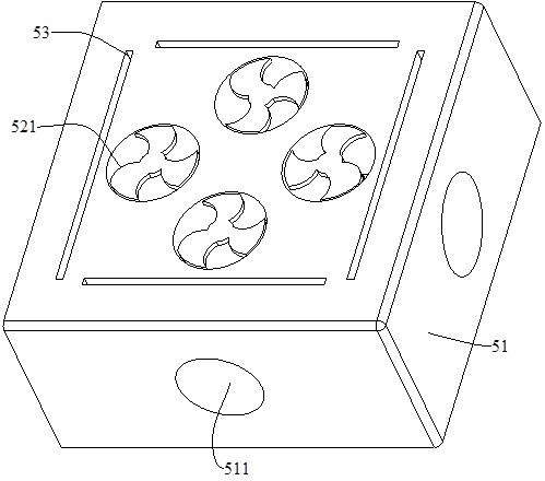
[0080]A plurality of guide chambers 53 are provided on the adjustment table 51, and each guide chamber 53 is adapted to a plugging vertical passage 5121 of a sealing chamber 512; A 45° inclined platform 5123 is set at the junction of the vertical blocking channel 5121 and the blocking horizontal channel 5122, and the 45° inclined platform 5123 ensures that the incident angle and the reflection angle are consistent, so that the high-pressure gas in the blocking cavity 512 can flow out; and the diversion cavity 53 includes a trapezoidal cavity 531 and a vertical cavity 532 that communicate with each other. The larger bottom surface of the trapezoidal cavity 531 communicates with the vertical cavity 532 , and the smaller bottom surface of the trapezoidal cavity 531 communicates with th...


PUM


Abstract

The invention relates to a sintering furnace for silicon nitride ceramic sintering and a working method of the sintering furnace. The sintering furnace for silicon nitride ceramic sintering comprisesa furnace body, a heating body arranged in the furnace body, a crucible borne on the heating body and a pipeline device for transmitting high-pressure gas, wherein the pipeline device is suitable forconveying the high-pressure gas to the position below the heating body. The continuous and uniform heating temperature is ensured, and the recrystallization phenomenon of a sintered alloy material isreduced; when the high-pressure gas is added into the furnace body through the pipeline device, the influence of the high-pressure gas on the crucible is reduced in cooperation with an air control device, meanwhile, the crucible is heated continuously and evenly, and materials in the crucible react sufficiently; and the temperature inside the furnace body is detected through a temperature sensor arranged on the furnace wall, so that the high-pressure gas with the proper temperature is selected to be introduced into the furnace body, and an air control system is further matched.

Description

technical field [0001] The invention relates to a sintering furnace, in particular to a sintering furnace for sintering silicon nitride ceramics and a working method thereof. Background technique [0002] Chinese patent application number: CN202010613549.3 discloses a neodymium-iron-boron vacuum sintering furnace, including a furnace body, a vacuum pump, a cleaning device, a cooling device, a heating device, and a placement device. Divided into two spaces, the sintering chamber and the cooling chamber, the cleaning device and the heating device are arranged in the sintering chamber, the cooling device is arranged in the cooling chamber, the placing device is slidably clamped on the inner wall on the right side of the furnace body, and the placing device is equipped with There is a driving device, a furnace cover is provided on the sintering chamber and the cooling chamber, the furnace cover is pivotally connected to the furnace body, and the vacuum pump is respectively conne...

Claims


Application Information

Patent Timeline
IPC IPC(8): F27B5/16F27B5/14F27B5/18
CPCF27B5/16F27B5/14F27B5/18F27B2005/161F27M2003/04
Inventor 杨文伍
Owner 宁波银瓷新材料有限公司
Why Eureka
Try Eureka