Motor rotor assembly and motor

A technology for motor rotors and components, applied in electric components, electrical components, synchronous machine parts, etc., can solve the problems of large size of the yoke, low structural strength, poor stability, etc., and achieve high structural strength, high power density, and stability. strong effect

Pending Publication Date: 2021-02-23
嘉兴弈承机电科技有限公司
View PDF1 Cites 1 Cited by
  • Summary
  • Abstract
  • Description
  • Claims
  • Application Information

AI Technical Summary

Problems solved by technology

[0004] Although the above solution solves the problem of large volume of the existing rotor yoke to a certain extent, since the permanent magnets and magnetic poles in this solution are fixed on the polygonal prism shaft by glue or screws, when the rotor rotates at high speed, under the action of centrifugal force The rotor may disintegrate, the structural strength is low, and the stability is poor

Method used


Image

  • Motor rotor assembly and motor
  • Motor rotor assembly and motor
  • Motor rotor assembly and motor

Examples


Embodiment 1

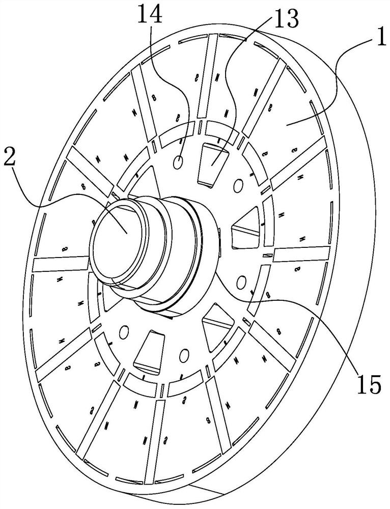
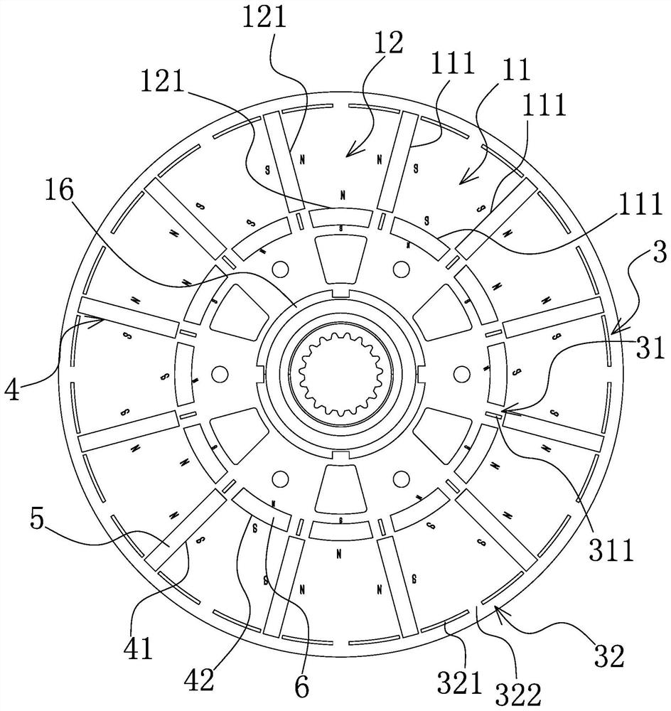
[0028] Such as Figure 1-2 As shown, the motor rotor assembly includes a rotor body 1 with a motor shaft 2 in the center. The rotor body 1 is a silicon steel sheet in the shape of a disc, and at least one end surface of the rotor body 1 has several S magnetic pole regions 11 and N magnetic poles in sequence in the circumferential direction. region 12 , and the S magnetic pole region 11 and the N magnetic pole region 12 are evenly staggered and adjacently distributed. Preferably, both end surfaces of the rotor body 1 here have S magnetic pole regions 11 and N magnetic pole regions 12, the S magnetic pole regions 11 on the two end surfaces of the rotor body 1 are arranged in one-to-one correspondence, and the N magnetic pole regions on the two end surfaces of the rotor body 1 12 one-to-one correspondence settings. At the same time, the size and shape of the S magnetic pole area 11 and the N magnetic pole area 12 here are the same, and the number of the S magnetic pole area 11 o...

Embodiment 2

[0039] The structure, principle and implementation steps of this embodiment are similar to those of Embodiment 1, the difference is that the outer magnetic isolation assembly 32 in this embodiment is a magnetic isolation coating covering the circumferential outer side of the rotor body 1; or, as Figure 5 As shown, the outer magnetic isolation assembly 32 includes arc-shaped recesses 323 uniformly formed on the outer peripheral edge of the rotor body 1 and recessed inward, and the arc-shaped recesses 323 are respectively located at two adjacent first permanent magnets 5 away from the rotor. There is a magnetic isolation layer 324 between one end of the center of the body 1 and outside the arc-shaped concave portion 323 .


PUM


Abstract

The invention belongs to the technical field of motor equipment, and particularly relates to a motor rotor assembly and a motor. The technical problem that an existing rotor is large in size is solved. The motor rotor assembly comprises a rotor body with a motor shaft in the center, the rotor body is a wafer-shaped silicon steel sheet, at least one end surface of the rotor body is circumferentially and sequentially provided with a plurality of S magnetic pole areas and N magnetic pole areas, and the S magnetic pole areas and the N magnetic pole areas are uniformly staggered one by one and areadjacently distributed. A rotor magnet yoke structure is cancelled, and the rotor structure is formed by the silicon steel sheets and the permanent magnets, so the size and weight of the rotor are reduced, and the loss is small when the rotor rotates. The silicon steel sheets are integrally formed, and are high in structural strength, the S and N magnetic pole areas at the two ends of the rotor body are arranged in a one-to-one correspondence manner, the magnetic isolation structure can prevent the S magnetic pole from being communicated with the N magnetic pole, the utilization rate of the permanent magnet is improved, the stability is high when the rotor rotates, and the power density of the motor is high.

Description

technical field [0001] The invention belongs to the technical field of motor equipment, and in particular relates to a motor rotor assembly and a motor. Background technique [0002] Axial permanent magnet motors are also called disc permanent magnet motors. Compared with other motors, they have the advantages of compact structure, high efficiency, and high power density, so they are getting more and more attention. Existing axial permanent magnet motors are generally composed of rotors, stators, end covers, casings, etc., and the existing rotors and stators generally have yokes, and the yokes on the rotors of axial permanent magnet motors do not produce The magnetic field only plays the role of magnetic force line transmission in the magnetic circuit, but the part of the rotor yoke corresponding to the stator cannot play the role of magnetic force line transmission, and due to the large volume and weight of the rotor yoke, the rotor itself will rotate. High loss, which und...

Claims


Application Information

Patent Timeline
Patent Type & Authority Applications(China)
IPC IPC(8): H02K1/27H02K16/04H02K21/02
CPCH02K1/27H02K1/278H02K1/2793H02K16/04H02K21/02
Inventor 马连芳
Owner 嘉兴弈承机电科技有限公司
Why Eureka
Try Eureka