
Frequency conversion control device and method for combined single-inductor double-output switching converter

A single-inductance, dual-output, switching converter technology, which is applied to output power conversion devices, electrical variable adjustment, control/regulation systems, etc., can solve the problem of large losses, low efficiency, and cross-effects of continuous conduction modes in pseudo-continuous conduction modes. problems, to achieve good effects of cross-influence suppression, high efficiency, and good transient performance

Inactive Publication Date: 2021-02-23
SICHUAN UNIV
View PDF18 Cites 4 Cited by
  • Summary
  • Abstract
  • Description
  • Claims
  • Application Information

AI Technical Summary

Problems solved by technology

[0003] The purpose of the present invention is to provide a combination type single-inductance dual-output switching converter frequency conversion control device and method, which is used to solve the serious crossover effect of continuous conduction mode in the single-conduction mode of single-inductance multi-output switch converter independent charging sequence in the prior art , The problem of large loss and low efficiency in the pseudo-continuous conduction mode

Method used


Image

  • Frequency conversion control device and method for combined single-inductor double-output switching converter
  • Frequency conversion control device and method for combined single-inductor double-output switching converter
  • Frequency conversion control device and method for combined single-inductor double-output switching converter

Examples


Embodiment 1

[0036] combined with figure 1 As shown, a combined single-inductance dual-output switching converter frequency conversion control device includes a first voltage detection circuit VS1, a second voltage detection circuit VS2, a first current detection circuit IS1, a second current detection circuit IS2, a third current detection circuit Detection circuit IS3, first drive circuit DR1, second drive circuit DR2, third drive circuit DR3, fourth drive circuit DR4, first voltage detection circuit VS1, second voltage detection circuit VS2, second current detection circuit IS2 and the first The three current detection circuits IS3 are respectively connected to the output branches of the single-inductance dual-output switching converter TD. When the topology structure of the single-inductance dual-output switching converter TD is as follows Figure 5 As shown, the first current detection circuit IS1 is used to detect the inductance circuit of the single-inductance dual-output switching ...

Embodiment 2

[0059] When the topology of the single-inductor dual-output switching converter TD is a single-inductor dual-output Boost converter, such as Figure 12 shown.

[0060] The device can also be used to control various converters with a single-inductance dual-output topology, such as Buck converters, Boost converters, Buck-boost converters, Bipolar converters, and the like.

Embodiment 3

[0062] The frequency conversion control method for a combined single-inductance dual-output switching converter includes a frequency conversion control device for a combined single-inductance dual-output switching converter, and the frequency conversion control device for a combined single-inductance dual-output switching converter and the converter according to figure 1 connected, including steps:

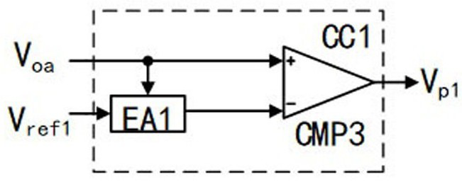
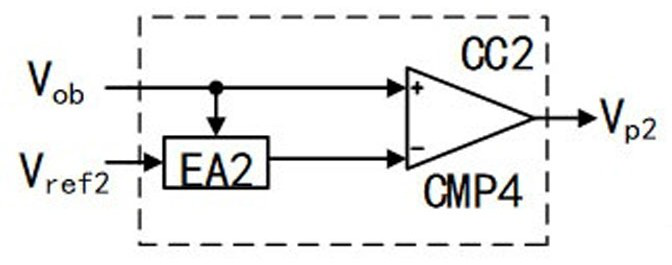
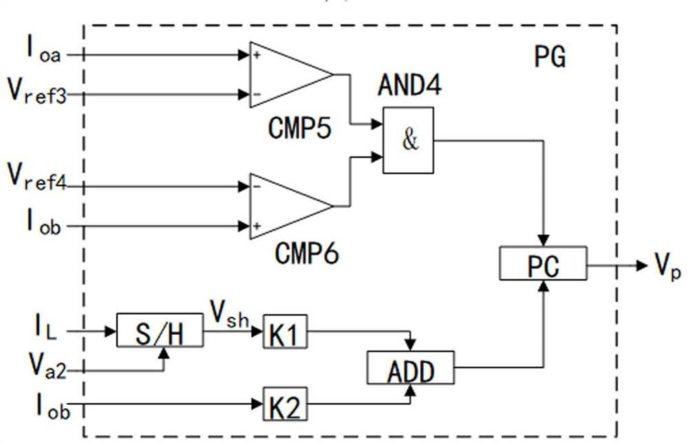
[0063] In each working cycle, the first current detection circuit IS1 detects the converter to obtain the inductor current I L , the first voltage detection circuit VS1 and the second voltage detection circuit VS2 detect the output voltages of the two output branches to obtain the signal V oa and signal V ob , the second current detection circuit IS2 and the third current detection circuit IS3 detect the load currents of the two output branches to obtain the output branch current I oa and the output branch current I ob ;

[0064] put the signal V oa sent to the first voltage ...


PUM


Abstract

The invention discloses a frequency conversion control method for a combined single-inductor double-output switching converter. A follow current reference value is dynamically adjusted according to the magnitude of a load current, dynamic follow current of the converter is realized, and meanwhile, the switching loss and conduction loss of a follow current switching tube are reduced by adopting a mode of combining an inductive current continuous conduction mode and a pseudo continuous conduction mode. The invention further discloses a frequency conversion control device for a combined single-inductor double-output switching converter. The method and the device have the advantages of good stability, high reliability, strong anti-interference capability, high load transient response speed, high efficiency and the like while keeping small cross influence among output branches, and can be used for controlling various converters of a single-inductor double-output topological structure.

Description

technical field [0001] The invention relates to the technical field of power electronic equipment, in particular to a frequency conversion control device and method for a combined single-inductance double-output switching converter. Background technique [0002] In recent years, portable electronic devices have been popularized on a large scale. In these devices, different modules often require different levels of voltage power supply. Therefore, the rapid development of portable devices has made people put forward higher requirements for the performance of multi-output power supplies. Compared with the traditional multi-output switching converter, the single-inductor multi-output switching converter has the characteristics of less magnetic components, small size, low cost, etc., and can independently control each output branch, and has a wide range of applications in portable devices prospect. According to the switching sequence of the inductor current in a unit cycle, the...

Claims


Application Information

Patent Timeline
Patent Type & Authority Applications(China)
IPC IPC(8): H02M3/158H02M1/08
CPCH02M1/08H02M3/158H02M3/1582H02M1/009
Inventor 贺明智林润泽周述晗唐嵩峰刘雪山陈雨竹周群杨成王指香
Owner SICHUAN UNIV
Learn More