
Gas-material separator

A technology of separator and air material, which is applied in the field of animal husbandry and can solve the problems of clogged filter material, trouble, and filter bag sticking of bag filter

Pending Publication Date: 2021-02-26
WUXI CULTIVATION MACHINERY
View PDF0 Cites 3 Cited by
  • Summary
  • Abstract
  • Description
  • Claims
  • Application Information

AI Technical Summary

Problems solved by technology

[0003] The following problems exist in the use of bag dust collectors: 1. Some materials contain moisture, or the dust they carry has strong hygroscopicity, which often causes the filter bags of the bag dust collector to stick and block the filter material; in order to ensure the normal operation of the bag dust collector, Necessary drying or heat preservation measures must be taken to ensure that the moisture in the gas will not condense; 2. Some types of bag filter workers have poor working conditions, and it is troublesome to enter the box when checking and replacing the filter bag; 3. Bag filter The filter bag of the dust collector has a certain limit on the ability to withstand the temperature; the temperature resistance of cotton and wool filter materials is 80-95 degrees, the temperature resistance of synthetic fiber filter materials is 200-260 degrees, and the temperature resistance of glass fiber filter materials is 280 degrees. When the flue gas has a higher temperature, measures must be taken to reduce the temperature of the flue gas; 4. The filter material of the bag filter itself is mostly cotton or glass fiber, so the effect will be relatively weak when filtering short fiber dust; 5. Bag filter It is necessary to manually clean the dust accumulated on the bag, otherwise the bag will be blocked, and the pressure in the pipeline cannot be discharged, which will affect the positive pressure of pneumatic conveying for feeding

Method used


Image

  • Gas-material separator
  • Gas-material separator
  • Gas-material separator

Examples


Embodiment Construction

[0023] The technical solutions of the present invention will be clearly and completely described below in conjunction with the accompanying drawings. Apparently, the described embodiments are some of the embodiments of the present invention, but not all of them. Based on the embodiments of the present invention, all other embodiments obtained by persons of ordinary skill in the art without making creative efforts belong to the protection scope of the present invention.

[0024] In describing the present invention, it should be understood that the terms "center", "longitudinal", "transverse", "length", "width", "thickness", "upper", "lower", "front", " Rear", "Left", "Right", "Vertical", "Horizontal", "Top", "Bottom", "Inner", "Outer", "Axial", "Radial", "Circumferential" The orientation or positional relationship indicated by etc. is based on the orientation or positional relationship shown in the drawings, and is only for the convenience of describing the present invention an...


PUM


Abstract

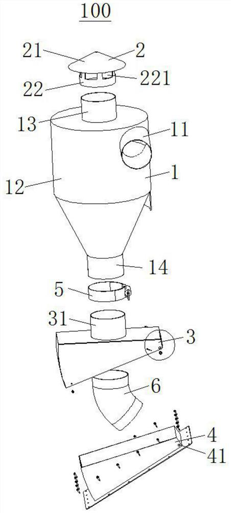
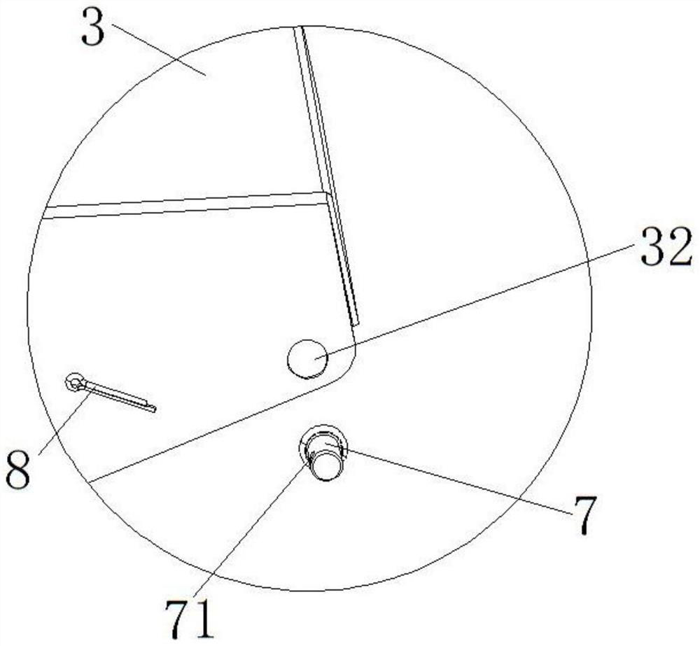
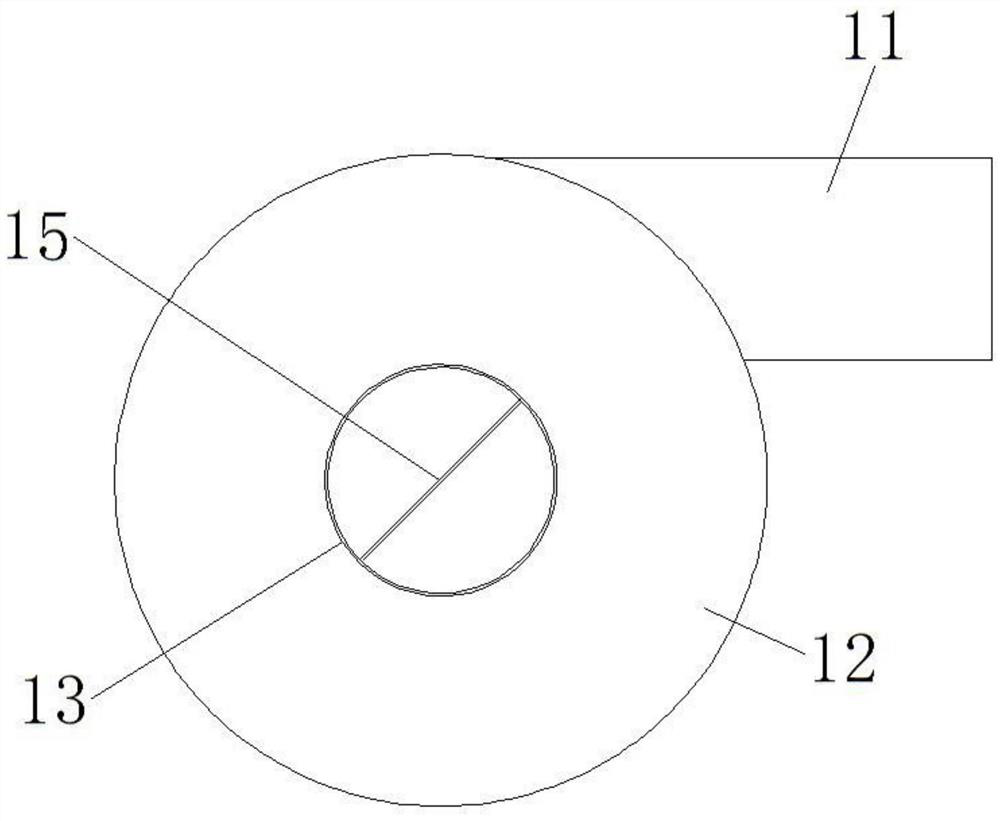
The invention provides a gas-material separator which is installed on a material tower. The gas-material separator comprises a cyclone dust collector, a rainproof cap, an adjusting connecting piece and a base, wherein the cyclone dust collector comprises a gas inlet and a barrel, the gas inlet is tangent to the side wall of the barrel, the gas inlet communicates with a cavity of the barrel, a gasoutlet is formed in the upper end of the barrel, the gas outlet is basically located over the central axis of the barrel, and a discharging opening is formed in the lower end of the barrel and basically located under the central axis of the barrel; and the rainproof cap is connected to the gas outlet, the adjusting connecting piece is connected to the discharging opening, and the adjusting connecting piece is arranged on the base through a pin shaft in an angle-adjustable mode. The gas inlet of the gas-material separator is connected with a positive-pressure pneumatic conveying pipeline for farm materials, the positive-pressure pneumatic conveying pipeline conveys the materials into the cyclone dust collector, gas is exhausted from the gas outlet, the materials fall into the material towerfrom the discharging opening, and dust in the materials separated by the cyclone dust collector can be effectively removed.

Description

technical field [0001] The invention relates to the technical field of animal husbandry, in particular to an air material separator. Background technique [0002] In animal husbandry and other breeding industries, pipelines are generally used to connect several material towers in the breeding area in series, and a bag filter is installed at a reasonable position, and then the dust generated by the positive pressure in the material tower is pneumatically conveyed by the negative pressure generated by the centrifugal fan Collected through the pipeline into the bag filter for dust removal. [0003] The following problems exist in the use of bag dust collectors: 1. Some materials contain moisture, or the dust they carry has strong hygroscopicity, which often causes the filter bags of the bag dust collector to stick and block the filter material; in order to ensure the normal operation of the bag dust collector, Necessary drying or heat preservation measures must be taken to ens...

Claims


Application Information

Patent Timeline
IPC IPC(8): B04C5/00B04B15/00B65G53/34
CPCB04B15/00B04C5/00B65G53/34
Inventor 黄晋徐进瑜邹斌
Owner WUXI CULTIVATION MACHINERY
Learn More