A fixing device for metal welding

A fixing device and metal welding technology, which is applied in the direction of welding equipment, auxiliary devices, auxiliary welding equipment, etc., can solve the problems of poor fixing effect of metal pipes, affect welding quality, and generate vibration, so as to achieve accurate fixing, save fixing time, The effect of lowering operating restrictions

Active Publication Date: 2022-07-19
中铁二十四局集团西南建设有限公司 +1
View PDF16 Cites 0 Cited by
  • Summary
  • Abstract
  • Description
  • Claims
  • Application Information

AI Technical Summary

Problems solved by technology

[0004] The existing welding fixtures have a poor fixing effect on metal pipes. Usually, circular hoops are used for fixing directly. In the process of welding, vibrations sometimes occur, and the vibration is caused by the extrusion of the pipes on the circular hoops. Because the fixing device itself has no components that can buffer the extrusion force, the circular hoop will be offset if it is squeezed for a long time, and the offset of the circular hoop during the process of fixing the round tube will easily cause the tube to deflect. Shift, thus affecting the welding quality

Method used


Image

  • A fixing device for metal welding
  • A fixing device for metal welding
  • A fixing device for metal welding

Examples


Embodiment 1

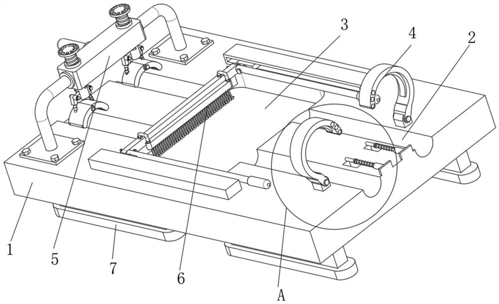
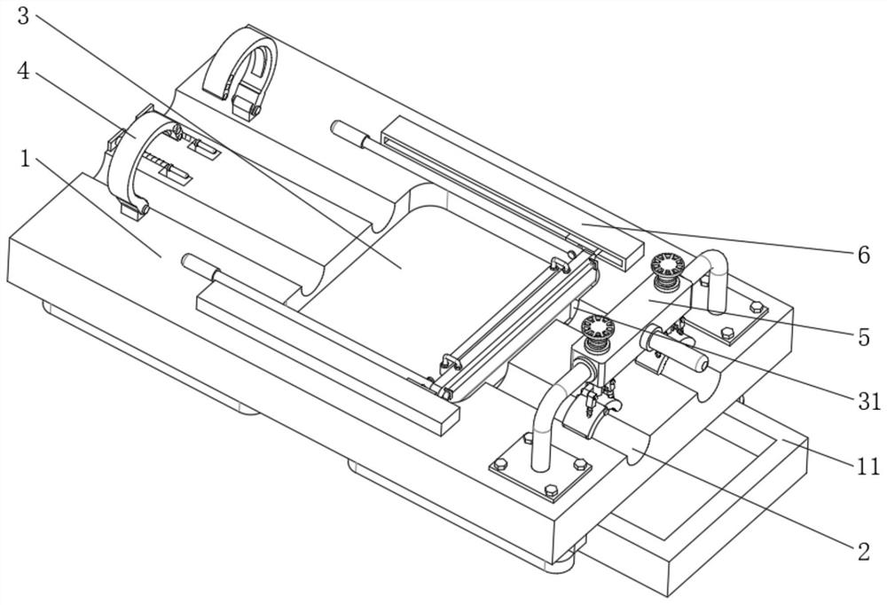
[0032] Example 1, as Figure 1-7 As shown, the present invention provides a fixing device for metal welding, comprising a workbench 1, a limit slot 2 is provided at both ends of the top of the workbench 1, and a top of the workbench 1 is located between the two limit slots 2. In the miscellaneous storage tank 3, the top of the worktable 1 is located at one end of the two limit grooves 2, and a rust removal assembly 4 is fixedly installed. The top of the workbench 1 is located on both sides of the miscellaneous storage tank 3 and a cleaning component 6 is provided on the top.

[0033] The specific settings and functions of the fastening device 5 will be described in detail below.

[0034] like figure 2 and image 3 As shown, the fastening device 5 includes a support shaft 51, two ends of the support shaft 51 are fixedly installed on one side of the two limiting grooves 2 respectively, the outer surface of the support shaft 51 is rotatably connected with a turning block 52, ...

Embodiment 2

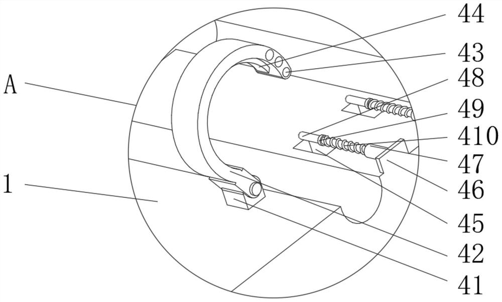
[0037] The specific settings and functions of the rust removal component 4 will be described in detail below.

[0038] like figure 2 and Figure 4 As shown, the rust removal assembly 4 includes a connector 41 and a slot 45. The connector 41 and the slot 45 are respectively arranged on both sides of the single limit slot 2 at the top of the workbench 1. The top of the connector 41 is hinged with a half hoop 42. A scraper 44 is fixedly installed on the opposite side of the half hoop 42 and the limit groove 2, a bump 46 is fixedly installed on the top of the worktable 1 at the edge, and a sleeve 47 is fixedly installed on the side wall of the outer surface of the bump 46. The inner wall of the tube 47 is slidably connected with a positioning pin 48, a limit ring 49 is provided on the outer surface of the positioning pin 48, and an elastic spring 410 is sleeved at one end of the positioning pin 48 between the limit ring 49 and the sleeve 47. The two ends are respectively fixedl...

Embodiment 3

[0041] The specific settings and functions of the cleaning component 6 will be described in detail below.

[0042] The cleaning assembly 6 includes a bar-shaped block 61. The top of the workbench 1 is located on both sides of the miscellaneous storage tank 3. The bar-shaped block 61 is fixedly installed. The inner wall of 62 is slidably connected with a slider 63, the opposite sides of the two sliders 63 are fixedly installed with a shaft 64, the outer surface of the shaft 64 is rotatably connected with a connecting rod 65, and the two connecting rods 65 are away from one end of the shaft 64 A connecting block 66 is fixedly installed, and a cleaning knife 67 and a brush 68 are fixedly installed on both sides of the outer surface of the connecting block 66. A return spring 69 is fixedly installed between the sliding block 63 and the opposite side of the chute 62. The interior of 3 is provided with a miscellaneous outlet 31, and the bottom of the workbench 1 is fixedly installed...


PUM


Abstract

The invention provides a fixing device for metal welding, which relates to the technical field of fixing devices for welding, and includes a workbench. Limiting grooves are formed on both ends of the top of the workbench, and the top of the workbench is located between the two limiting grooves. A miscellaneous storage tank is opened between the two, the top of the worktable is located at one end of the two limit grooves, and a rust removal component is fixedly installed, and the top of the worktable is located at the other end of the two limit grooves. A fastening device is fixedly installed. In the present invention, the fixing is made more precise by adjusting the position twice, and a buffer spring is provided at the same time, and the rebound force of the buffer spring can effectively offset the vibration generated during welding, so that the traditional circular hoop will not be squeezed for a long time. Offset, thus causing the pipe offset to affect the welding quality, and at the same time, the inner wall of the clamping hoop is provided with anti-skid strips, which can further prevent the pipe from slipping during welding and improve the welding accuracy.

Description

technical field [0001] The present invention relates to the technical field of welding fixing devices, in particular to a metal welding fixing device. Background technique [0002] With the development of society, the forging and application of metal pipelines in my country are becoming more and more extensive. Some pipelines are devices used to transport gases, liquids or fluids with solid particles. Due to their unique characteristics, pipelines are widely used in many Industry, many fields, pipelines are widely used, mainly used in water supply, drainage, heating, gas supply, long-distance transportation of oil and natural gas, agricultural irrigation, water conservancy projects and various industrial installations. [0003] As a type of pipeline, metal pipes are widely used in the construction process of chemical buildings. In the process of prefabrication of metal pipes, metal pipes often need to be welded, and butt welding and fillet welding are required according to th...

Claims


Application Information

Patent Timeline
Patent Type & Authority Patents(China)
IPC IPC(8): B23K37/053B08B1/00B08B9/023B08B15/04B23K37/00
CPCB23K37/0533B23K37/00B08B1/002B08B1/005B08B1/008B08B15/04B08B9/023
Inventor 喻文杰李小飞易春红贾刊和
Owner 中铁二十四局集团西南建设有限公司
Why Eureka
Try Eureka