Vacuum thermoplastic laminating process and equipment for achieving process
A bonding equipment, vacuum heating technology, applied in printed circuits, chemical instruments and methods, electrical components, etc., can solve problems such as height difference of bonding surface, residual air bubbles, limited effect, etc.
- Summary
- Abstract
- Description
- Claims
- Application Information
AI Technical Summary
Problems solved by technology
Method used
Image

Examples
Embodiment 1
[0121] Embodiment 1 Laminating equipment
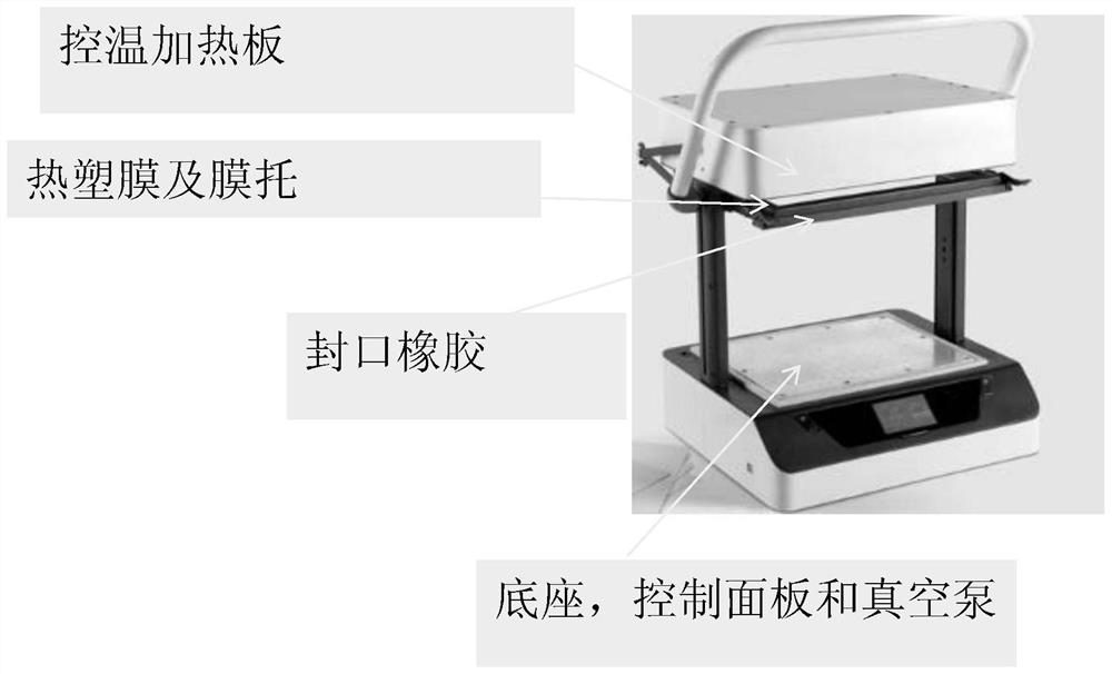
[0122] The main components (from top to bottom) of the bonding equipment of the present invention and their mode of action are as follows:
[0123] 1) Temperature-controlled heating plate: The thermoplastic film is heated by means of heat radiation through resistance heating. The temperature-controlled heating plate is supported and coupled to the top of the device through two pillars coupled to the base. The size of the heating zone of the temperature control heating plate is 32cm*28cm. The temperature of the temperature-controlled heating plate is regulated through the control panel. The height of the pillars is 30cm.
[0124] 2) Thermoplastic film and film support: After the thermoplastic film is heated to the set softening temperature, the thermoplastic film is lowered to the base by holding the film support. The film support is movably connected to the two pillars supporting the temperature control heating plate, and its lock...
Embodiment 2
[0129] Embodiment 2 Bonding process 1
[0130] 1) Place the glue-containing samples that need to be bonded (including the upper bonding material anodized aluminum, tesa58484 and the lower bonding material polycarbonate in sequence) on the vacuum platform (that is, a uniformly perforated metal plate, the thickness of the metal plate 1mm, the hole distribution density is 16pcs / 1cm 2 , the hole diameter is 1mm);
[0131] 2) Install a thermoplastic film with a specific softening temperature (such as HIPS high-density polystyrene, the size is 31cm*26cm, and the softening temperature is 130°C) on the fixture (ie, the film holder);
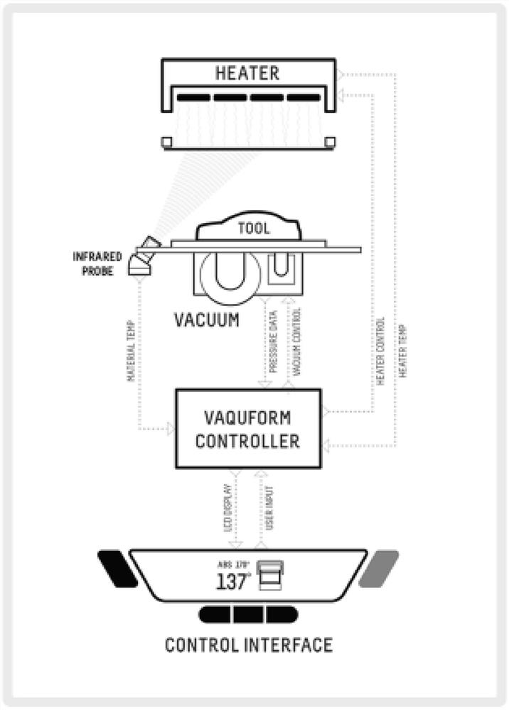
[0132] 3) Set the infrared detection mold temperature parameter to 130 degrees, and the vacuum parameter to 0.2bar or 0.5bar or 0.9bar;
[0133] 4) Pull up the thermoplastic film close to the heating surface (that is, the temperature control heating plate, set the heating temperature to 165°C), and heat the surface temperature of the thermoplastic film...
Embodiment 3
[0137] Embodiment 3 Bonding process 2
[0138] Same as Example 2, the difference is: use high-temperature reactive glue such as tesa 58474 and other hot melt glue to replace the glue used in Example 2; and after step 6), it also includes a step: vacuum defoaming treatment, the specific steps are as follows: will go through step 6) The final semi-reacted rubber-containing sample is thrown into a high-temperature degassing machine to continue the pressurized reaction to obtain better adhesion or other higher mechanical requirements.
PUM
| Property | Measurement | Unit |
|---|---|---|
| Length | aaaaa | aaaaa |
| Height | aaaaa | aaaaa |
| Softening temperature | aaaaa | aaaaa |
Abstract
Description
Claims
Application Information
PatSnap Eureka turns technology decisions into work you can execute. Powered by our Innovation Knowledge Graph, it runs expert workflows across engineering, life sciences, materials and intellectual property. Get your review-ready output in minutes.


