Spiral-flow type micro-nano bubble generator and generation method thereof

A technology of nano-bubbles and generators, applied in chemical instruments and methods, biological treatment devices, sustainable biological treatment, etc., to achieve the effects of increasing absolute speed, shortening gas path, processing difficulty and cost reduction

Pending Publication Date: 2021-02-26
陕西超微环境科技有限公司
View PDF0 Cites 8 Cited by
  • Summary
  • Abstract
  • Description
  • Claims
  • Application Information

AI Technical Summary

Problems solved by technology

[0004] The technical problem to be solved by the present invention is to aim at the deficiencies in the above-mentioned prior art, and disclose a swirling micro-nano bubble generator and its generation method, which adopts a static multi-stage cascade and the last stage is a hollow blade structure, and utilizes The cascade converts the water flow from a straight flow to a swirling flow. Through the change of the installation angle of the multi-stage cascade, the head provided by the water pump is efficiently converted into a high-speed circumferential water flow velocity in a short process, which is generated by the shearing of the rotating water flow on the gas. Micro-nano bubbles, reliable operation and not easy to clog

Method used


Image

  • Spiral-flow type micro-nano bubble generator and generation method thereof
  • Spiral-flow type micro-nano bubble generator and generation method thereof
  • Spiral-flow type micro-nano bubble generator and generation method thereof

Examples


specific Embodiment approach

[0035] It should be noted that the structures, proportions, sizes, etc. shown in the drawings attached to this specification are only used to match the content disclosed in the specification, for those who are familiar with this technology to understand and read, and are not used to limit the implementation of the present invention Any modification of the structure, change of the proportional relationship or adjustment of the size shall still fall within the scope of the technical content disclosed in the present invention without affecting the effect and the purpose of the present invention. within the scope covered.

[0036] At the same time, terms such as "upper", "lower", "left", "right", "middle" and "one" quoted in this specification are only for the convenience of description and are not used to limit this specification. The practicable scope of the invention and the change or adjustment of its relative relationship shall also be regarded as the practicable scope of the...

Embodiment 1

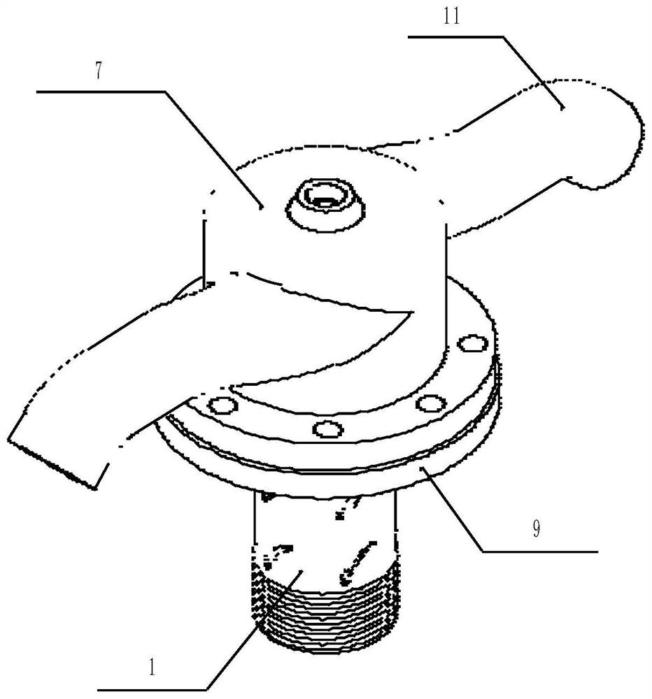
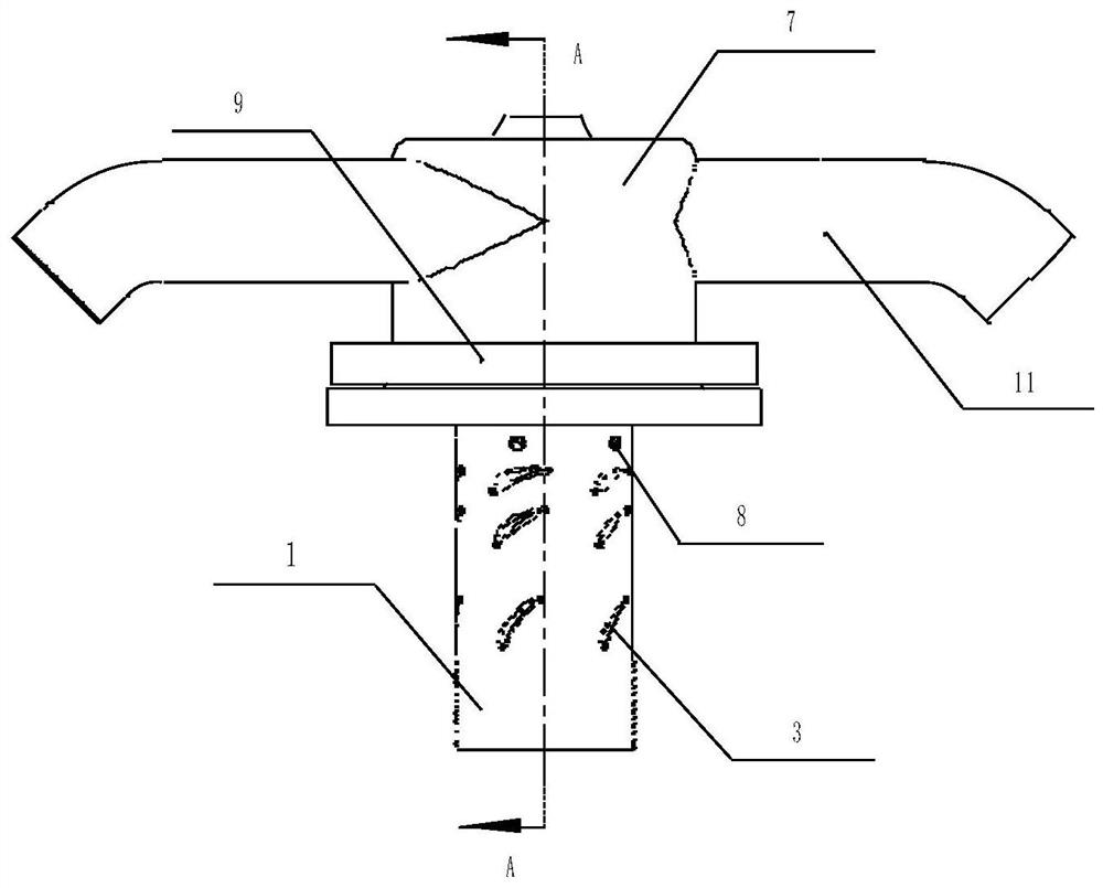
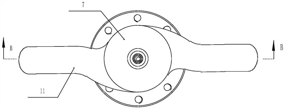
[0038] Such as Figure 1 to Figure 7 As shown, it shows a specific embodiment of the present invention. As shown in the figure, a swirl type micro-nano bubble generator disclosed by the present invention includes an outer cylinder 1, a blade shaft 2, a blade 3, a sealing ring 4, Sleeve 5, intake throat pipe 6, volute 7, top wire 8, mounting plate 9, cavitator 10, spinning cylinder 11, positioning pin 12, connecting screw 13 and toothed gasket 14, the volute 7. Two spinning cylinders 11 are evenly distributed along the circumferential direction on the outer wall, and the spinning cylinders 11 are connected to the volute 7. The bottom of the volute 7 is provided with a flange and the center of the volute 7 is provided with a through hole. An annular groove is arranged on the bottom surface of the flange at the bottom of the volute 7 and a sealing ring 4 is installed in the annular groove. The mounting plate 9 is fixed on the flange at the bottom of the volute 7 by screws and the...

Embodiment 2

[0047] A method for generating a swirling micro-nano bubble generator, characterized in that it comprises the following steps:

[0048] Step 1: Fix the swirl-type micro-nano bubble generator on the bearing platform in the sewage tank, and ensure that the outlet of the spinning cylinder 11 is located near the sewage water surface, and the top of the air inlet pipe 6 is located above the sewage water surface;

[0049] Step 2: Connect the outlet of the sewage pump to the bottom of the outer cylinder 1 through a pipeline. The sewage pump pumps sewage through multiple sets of blades 3 between the blade shaft 2 and the outer cylinder 1 to generate rotating water flow, and forms a negative flow after the final blade 3. The air is sucked in by pressure, and the air enters the sleeve 5 through the inlet throat 6, the air in the sleeve 5 enters the cavitator 10 through the air intake slot, and all the air exits through the airfoil-shaped hollow blade on the cavitator 10. The slit is she...


PUM

PropertyMeasurementUnit
thicknessaaaaaaaaaa
thicknessaaaaaaaaaa
thicknessaaaaaaaaaa

Abstract

The invention discloses a spiral-flow type micro-nano bubble generator and a generation method thereof.The spiral-flow type micro-nano bubble generator is mainly characterized in that two spiral-flowstarting cylinders are evenly distributed on the outer wall of a volute in the circumferential direction and communicated with the volute, a flange plate is arranged at the bottom of the volute, a through hole is formed in the center of the volute, and an outer cylinder is installed in a center hole of an installation disc; a plurality of grades of blades are arranged on a blade shaft, an air inlet throat pipe is installed at the top end of a sleeve, the bottom of the sleeve is installed at the top end of a cavitator through a positioning pin, a tooth-shaped gasket is installed between the bottom face of the sleeve and the top face of the cavitator, and the cavitator is installed in a positioning hole in the top end of the blade shaft. A static multi-stage cascade is adopted, the last stage is of a hollow blade structure, water flow is converted into rotational flow from horizontal flow through the cascade, the lift provided by the water pump is efficiently converted into high-speed circumferential water flow speed in a short process through the change of the installation angle of the multi-stage cascade, and micro-nano bubbles are generated by shearing gas through rotating water flow. The generator is reliable in operation and less susceptible to clogging.

Description

technical field [0001] The invention relates to the technical field of environmental protection equipment, in particular to a swirling micro-nano bubble generator and a generating method thereof. Background technique [0002] Aerobic biological treatment is the most common treatment unit in the current sewage treatment process, and the aerator is the core equipment of this unit. The main function of the aerator is to oxygenate the water body, ensure the normal life activities of microorganisms, prevent the sludge from settling, and ensure the full contact between the air and the organic matter in the sludge and sewage. [0003] The existing main types of aerators have the following problems: (1) The gas-liquid mixing position is located at the trailing edge point of the inner shaft end of the device. Although the negative pressure is relatively large, which is good for air intake, the velocity here is very small (that is, the radius is zero , so the circumferential velocity...

Claims


Application Information

Patent Timeline
Patent Type & Authority Applications(China)
IPC IPC(8): C02F3/02
CPCC02F3/02C02F2203/006Y02W10/10
Inventor 张晓博
Owner 陕西超微环境科技有限公司
Why Eureka
Try Eureka