Cooling system and method for hydrogen storage container of hydrogen refueling station

A technology for hydrogen storage containers and hydrogen refueling stations, which is applied to container filling methods, container discharge methods, pressure vessels, etc., and can solve problems such as excessive temperature rise, high temperature of hydrogen storage containers, hydrogen leakage and combustion, and achieve the elimination of safety hidden effect

Pending Publication Date: 2021-02-26
正星氢电科技郑州有限公司
View PDF0 Cites 5 Cited by
  • Summary
  • Abstract
  • Description
  • Claims
  • Application Information

AI Technical Summary

Problems solved by technology

[0004] The invention provides a cooling system and method for a hydrogen storage container of a hydrogen refueling station, aiming to solve the safety problems caused by excessive temperature, excessive temperature rise and hydrogen leakage and combustion of the hydrogen storage container during use

Method used


Image

  • Cooling system and method for hydrogen storage container of hydrogen refueling station
  • Cooling system and method for hydrogen storage container of hydrogen refueling station
  • Cooling system and method for hydrogen storage container of hydrogen refueling station

Examples


Embodiment 1

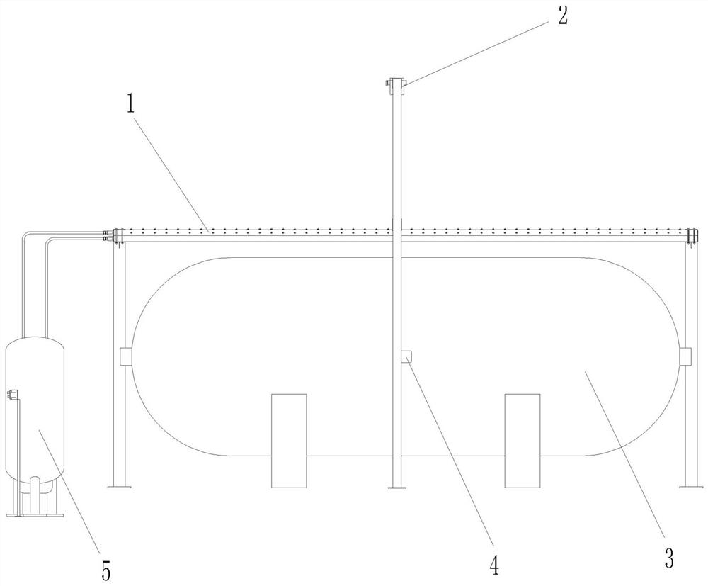
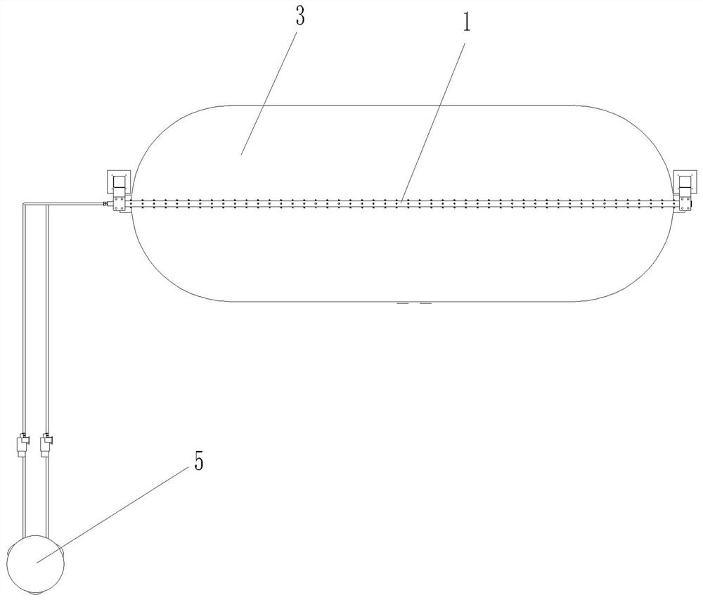
[0040] Embodiment 1: A hydrogen storage container cooling system for a hydrogen refueling station, see Figure 1 to Figure 7 ,include:

[0041] The spray mechanism includes an atomized water distribution chamber 20 arranged above the hydrogen storage tank 3, and a plurality of atomized nozzles 15 connected to the atomized water distribution chamber. The atomized water distribution chamber 20 is installed and used via a corresponding water supply The pipe and the spray electric ball valve are connected to the corresponding stabilized water supply system 5;

[0042] The spraying mechanism includes a spraying water distribution chamber 21 arranged above the hydrogen storage tank 3, and a plurality of spray holes 16 communicating with the spraying distribution water chamber 21, and the spraying distribution water chamber 21 passes through the corresponding water supply The pipe and the spray electric ball valve are connected to the stabilized water supply system 5; the atomizatio...

Embodiment 2

[0044] Embodiment 2 A method for cooling the hydrogen storage container of a hydrogen refueling station is implemented based on the arrangement of the hydrogen storage container cooling system described in Embodiment 1, see Figure 8 , Figure 9 , including the following steps:

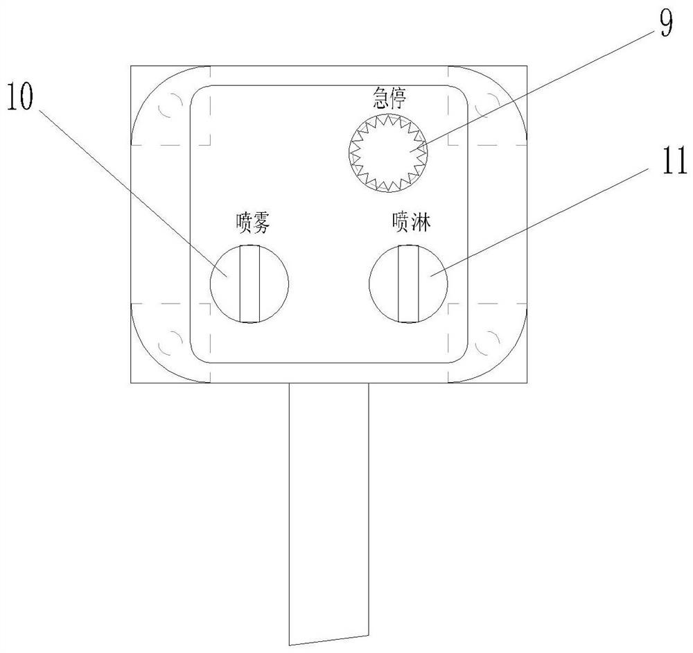
[0045] (1) Emergency stop control

[0046] Press the emergency stop button STP, the cooling system is in an emergency stop state, the system automatically closes the spray electric ball valve YV01 and the spray electric ball valve YV02, and generates an alarm message and sends out an alarm signal at the same time. Rotate the emergency stop button STP and pop up automatically, the emergency stop button STP is in the reset state, and the cooling system enters the automatic operation state.

[0047] (2) Spray control

[0048] see Figure 8 , turn on the spray knob switch SA01 on the explosion-proof operation column, the control unit controls to open the spray electric ball valve YV01, the cooling wat...


PUM


Abstract

The invention discloses a cooling system and method for a hydrogen storage container of a hydrogen refueling station, and aims to solve the safety problems caused by over-high temperature, over-fast temperature rise and leaked gas flammability in the use process of the hydrogen storage container. The cooling system mainly comprises a spraying mechanism, a sprinkling mechanism and a control unit, all of which are configured at the same time. Spraying or sprinkling is automatically controlled after logic processing by collecting the temperature of the hydrogen storage container, the temperatureof a tank field environment, signals of a tank field flame detector and signals of related buttons, and therefore the cooling function of the hydrogen storage container is achieved. The problems thatthe temperature is too high, and temperature rise is too fast in the using process of the hydrogen storage container can be effectively solved, so that potential safety hazards are eliminated. When hydrogen leakage combustion occurs in a hydrogen storage container area pipeline, spraying cooling is carried out on the hydrogen storage container, and the risk of explosion caused by failures of the hydrogen storage container is avoided.

Description

technical field [0001] The invention relates to the technical field of safe filling of combustible gas, in particular to a cooling system and method for a hydrogen storage container of a hydrogen refueling station. Background technique [0002] The hydrogen storage containers (such as tanks or bottle groups) of hydrogen refueling stations store hydrogen at a pressure of 20MPa, 45MPa and 90MPa, and the operating temperature cannot exceed 85°C. The compression or decompression of hydrogen will release heat, and the hydrogen temperature in the container will rise too fast during the filling process of the hydrogen storage container, which may cause the risk of exceeding the operating temperature range of the container, posing safety hazards in use. [0003] The hydrogen storage container is an important hydrogen refueling facility in a hydrogen refueling station. It is located in a flammable and explosive dangerous place, and the hydrogen storage pressure is high. In addition, ...

Claims


Application Information

Patent Timeline
Patent Type & Authority Applications(China)
IPC IPC(8): F17C1/00F17C5/06F17C13/02F17C13/12
CPCF17C1/00F17C5/06F17C13/026F17C13/123F17C2250/03F17C2260/042Y02E60/32Y02P90/45
Inventor 周亮李明昕黄景龙
Owner 正星氢电科技郑州有限公司
Why Eureka
Try Eureka