Eureka AIR delivers breakthrough ideas for toughest innovation challenges, trusted by R&D personnel around the world.

Software architecture design method for spaceflight embedded system

An embedded software and embedded system technology, applied in the field of software engineering, can solve problems such as the lack of embedded system software architecture, achieve the effects of avoiding code defects, realizing online fault diagnosis and repair, and reducing workload

Active Publication Date: 2021-02-26
北京京航计算通讯研究所
View PDF8 Cites 0 Cited by
  • Summary
  • Abstract
  • Description
  • Claims
  • Application Information

AI Technical Summary

Problems solved by technology

[0004] In view of the above analysis, the present invention aims to disclose a software architecture design method for aerospace embedded systems, solve the problem of lack of general embedded system software architecture in the field of aerospace embedded software engineering, and improve the reliability of software architecture

Method used


Image

  • Software architecture design method for spaceflight embedded system
  • Software architecture design method for spaceflight embedded system
  • Software architecture design method for spaceflight embedded system

Examples


Embodiment 1

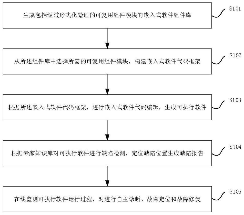
[0047] This embodiment discloses an embedded software architecture design method for aerospace embedded systems, such as figure 1 shown, including the following steps:

[0048] Step S101, generating an embedded software component library, the embedded software component library includes formally verified reusable components;

[0049] Step S102, selecting required reusable components from the embedded software component library, and constructing an embedded software code framework;

[0050] Step S103, according to the embedded software code framework, edit the embedded software code to generate executable software;

[0051] Step S104, performing defect detection on the generated executable software according to the expert knowledge base, locating the defect location to generate a defect report, and performing defect repair;

[0052] Step S105 , online monitoring of the running process of the executable software, and performing self-diagnosis, fault location and fault repair. ...

Embodiment 2

[0088] This embodiment specifically describes the data analysis layer CAN bus data management architecture design method, such as Figure 5 shown, including the following steps:

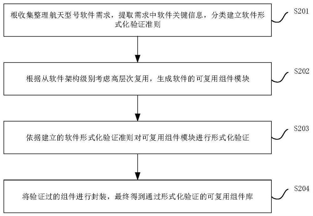
[0089] Step S501, generating a data management layer CAN bus data management reusable component library including formally verified reusable components;

[0090] Specifically include:

[0091] 1) Extract the CAN interface verification criteria in the requirements according to the requirements documents such as the aerospace system design description of the aerospace model software, the requirements specification description, and the interface communication protocol file;

[0092] 2) Design reusable components for the CAN bus data management of the data management layer from the software architecture level;

[0093] 3) According to the established CAN interface verification criteria, formally verify the CAN bus data management reusable components of the data analysis layer,

[0094] 4) Encapsulate ...


PUM


Abstract

The invention relates to a software architecture design method for a spaceflight embedded system, which comprises the following steps: generating an embedded software component library which comprisesreusable components subjected to formalization verification; selecting a required reusable component from the embedded software component library, and constructing an embedded software code framework; according to the embedded software code framework, carrying out embedded software code editing, and generating executable software; carrying out defect detection on the generated executable softwareaccording to an expert knowledge base, generating a defect report by locating the defect position, and carrying out defect repairing; and monitoring the operation process of the executable software on line, and carrying out autonomous diagnosis, fault positioning and fault repairing. The software development automation technology can be enriched, the software development efficiency is improved, the protocol development period is shortened, online fault diagnosis and repair are achieved, and the safety and robustness of codes are improved.

Description

technical field [0001] The invention belongs to the technical field of software engineering, and in particular relates to a software architecture design method for aerospace embedded systems, which is applied in the development process of aerospace embedded software. Background technique [0002] With the rapid development of aerospace applications, its complex task requirements require that the algorithms and processing of aerospace embedded software tend to be highly integrated and intelligent, and the scale and complexity of software are further improved. higher requirements. At present, the research and development of aerospace embedded software mainly adopts the task customization development mode. Due to the use of different software architectures, the inheritance between model software is weak, which affects the software development efficiency and the quality of software products. [0003] Regarding software development architecture issues, even if the software archi...

Claims


Application Information

Patent Timeline
Patent Type & Authority Applications(China)
IPC IPC(8): G06F8/36G06F8/35G06F11/36
CPCG06F8/36G06F8/35G06F11/3608
Inventor 张晛张玉王颖刘军丁敏高飞
Owner 北京京航计算通讯研究所
Why Eureka
Eureka Blog
Learn More