Varnished wire automatic processing equipment

A processing equipment, enameled wire technology, applied in heat treatment equipment, conductor/cable insulation, electrical components, etc., can solve the problems of poor enameled wire gloss, loose wires, increase economic benefits, etc., to reduce operating costs and improve work efficiency. Efficiency, the effect of increasing economic benefits

Active Publication Date: 2021-02-26
湘潭市霞城电工有限公司
View PDF3 Cites 3 Cited by
  • Summary
  • Abstract
  • Description
  • Claims
  • Application Information

AI Technical Summary

Problems solved by technology

[0004] The invention provides an enameled wire automatic processing equipment, which can improve the comfort level of the enameled wire automatic processing equipment, improve the working efficiency of the enameled wire automatic processing equipment when unwinding, and at the same time protect the wires, effectively avoiding damage caused by additional heating energy. The wire is annealed to reduce the operating cost of the enterprise and increase the economic benefits. At the same time, the advantages of the paint quality of the wire are mentioned, which solves the problem that the existing enameled wire needs to go through the pay-off barrel to pay off the processing line during the production process. During the process, because the radius of the cross-section of the pay-off and take-up reels is equal, but winding, the outermost circumference radius of the full pay-off reel is obviously larger than that of the take-up reel, which is wrapped around the wire to be processed. The length of the circumference of the cross-section, and the pay-off cylinder is constantly paying off the wire during the p...

Method used


Image

  • Varnished wire automatic processing equipment
  • Varnished wire automatic processing equipment
  • Varnished wire automatic processing equipment

Examples


Embodiment Construction

[0021] The following will clearly and completely describe the technical solutions in the embodiments of the present invention with reference to the accompanying drawings in the embodiments of the present invention. Obviously, the described embodiments are only some, not all, embodiments of the present invention. Based on the embodiments of the present invention, all other embodiments obtained by persons of ordinary skill in the art without making creative efforts belong to the protection scope of the present invention.

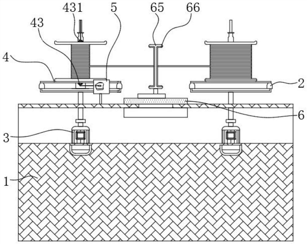
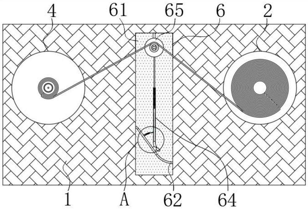
[0022] see Figure 1-5, an enameled wire automatic processing equipment, comprising a fixed table 1, the left side of the upper surface of the fixed table 1 is movably socketed with a wire take-up device 4, and the right side of the upper surface of the fixed table 1 is movably socketed with an outlet barrel 2 , the middle part of the upper surface of the fixed table 1 is fixedly connected with a tension adjustment device 6, and the bottom of the inner cavity ...


PUM


Abstract

The invention relates to the technical field of varnished wire processing, and discloses varnished wire automatic processing equipment which comprises a fixed table, the left side of the upper surfaceof the fixed table is movably sleeved with a take-up device, and the right side of the upper surface of the fixed table is movably sleeved with a wire outlet barrel. According to the varnished wire automatic processing equipment, through cooperation of a wire outlet barrel, a servo motor, a wire take-up device and a tension adjusting device, the pay-off tension can be kept, and the fixed-point movable connection of a vertical direction adjusting device and a fixed inclined rod in the tension adjusting device and the coincidence degree between an arc-shaped rod and an arc-shaped barrel in thehorizontal direction adjusting device are utilized, and the deviation angle of the vertical direction adjusting device is adjusted; when paying-off on the wire outlet barrel body is fast, the verticaldirection adjusting device is adjusted to drive a protective sleeve on a limiting barrel to do anticlockwise centrifugal motion, so that the paying-off comfort of the varnished wire automatic processing equipment is improved, and the working efficiency of the varnished wire automatic processing equipment during paying off is improved, and meanwhile, a wire is protected.

Description

technical field [0001] The invention relates to the technical field of enameled wire processing, in particular to automatic enameled wire processing equipment. Background technique [0002] Enameled wire is a main variety of winding wire, which is composed of conductor and insulating layer. The bare wire is annealed and softened, and then painted and baked for many times. However, it is necessary to produce products that meet both standard requirements and customer requirements. It is not easy. It is affected by raw material quality, process parameters, production equipment, environment and other factors. Therefore, the quality characteristics of various enameled wires are different, but they all have four major properties: mechanical properties, chemical properties, electrical properties, and thermal properties. [0003] During the production process of the existing enameled wire, it needs to go through the pay-off barrel to pay off the wire to be processed. The radius of ...

Claims


Application Information

Patent Timeline
IPC IPC(8): H01B13/00H01B13/06H01B13/16
CPCH01B13/0036H01B13/0016H01B13/065H01B13/165
Inventor 李云辉杨四龙
Owner 湘潭市霞城电工有限公司
Why Eureka
Try Eureka