Shared power bank

A power bank and wireless charging technology, which is applied in the direction of current collectors, circuit certification, electric vehicles, etc., can solve the problems of high product use and maintenance costs, increased maintenance costs of charging cabinets, and contact corrosion, so as to improve battery life and reduce Effect of contact oxidation or corrosion problems

Pending Publication Date: 2021-02-26
猪草微(深圳)电子有限公司
View PDF0 Cites 0 Cited by
  • Summary
  • Abstract
  • Description
  • Claims
  • Application Information

AI Technical Summary

Problems solved by technology

[0005] Shared power bank metal contacts, with the increase in frequency of use, on the one hand, the metal contacts will wear out, on the other hand, due to the user's habit of unconsciously touching the metal contacts, the sweat on the hands will remain on the contacts. As a point, long-term contact corrosion will lead to poor communication and charging between the power bank and the cabinet, resulting in the failure of the shared power bank to be charged normally or the failure of the user to rent a normal shared power bank, resulting in the failure of the shared power bank and the charging cabinet. Increased maintenance costs, resulting in a very bad user experience
[0006] On the other hand, in the process of returning the charging treasure, the user will inevitably have bad returning habits and incorrect use methods, which may easily lead to failure of the metal thimble of the charging cabinet. After the shared charging treasure enters the shared charging cabinet, there is no way to share the charging cabinet. Identifying the power bank, on the one hand, there is no way to charge the shared charging normally, and on the other hand, the background cannot correctly handle the action that the user has returned the shared power bank. The manufacturer of the shared power bank needs to manually check and take out the power bank. Repair and disposal, product usage and maintenance costs are also h

Method used


Image

  • Shared power bank
  • Shared power bank
  • Shared power bank

Examples


Embodiment Construction

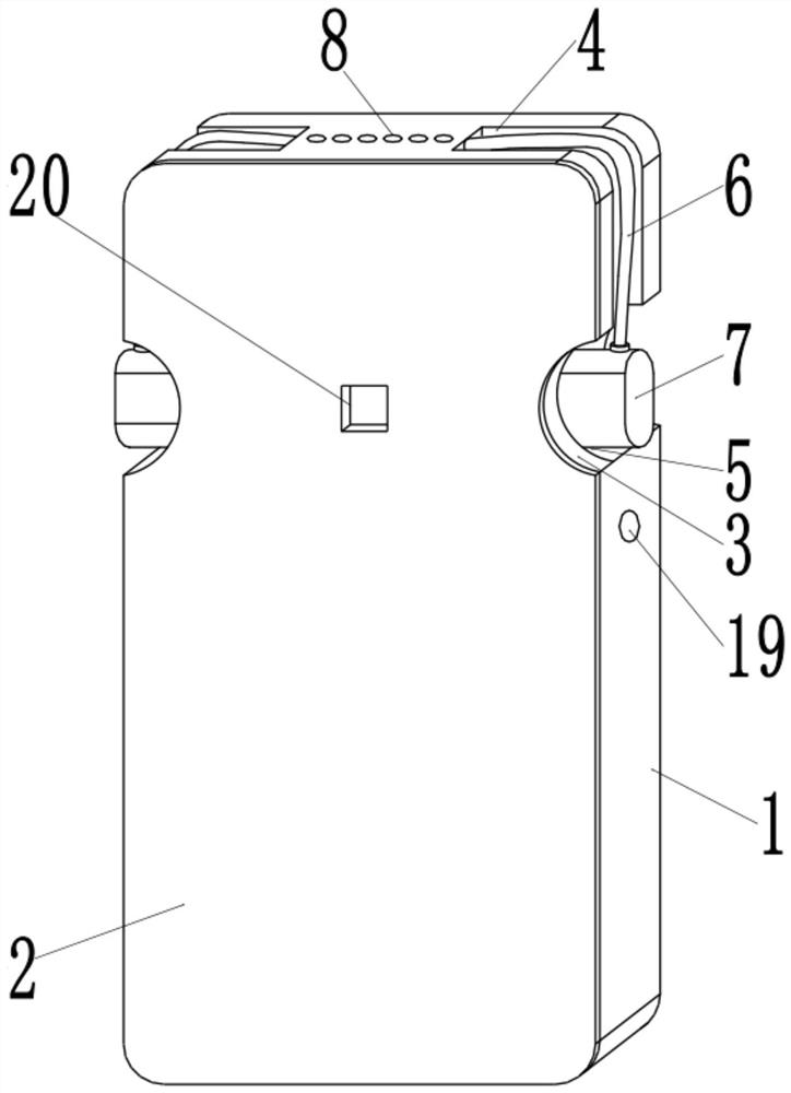
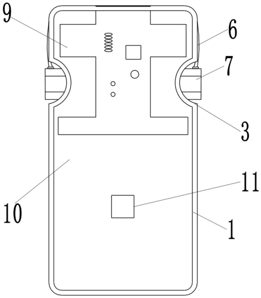
[0039] The following will be combined with Figure 1 to Figure 4 The present invention is described in detail, and the technical solutions in the embodiments of the present invention are clearly and completely described. Apparently, the described embodiments are only some of the embodiments of the present invention, not all of them. Based on the embodiments of the present invention, all other embodiments obtained by persons of ordinary skill in the art without making creative efforts belong to the protection scope of the present invention.

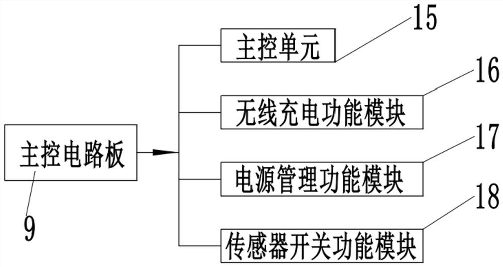
[0040] The present invention provides a shared power bank through improvement, such as Figure 1-4 As shown in the figure, it includes a main control circuit board 9, and the main control circuit board 9 is provided with a main control unit 15, a wireless charging function module 16, a power management function module 17 and a sensor switch function module 18;

[0041] The main control unit collects the state information of the power bank...


PUM


Abstract

The invention relates to the field of power banks, in particular to a shared power bank, and the shared power bank comprises a main control circuit board; a main control unit, a wireless charging function module, a power management function module and a sensor switch function module are arranged on the main control circuit board; the wireless charging function module comprises a wireless chargingtransmitting and receiving integrated coil module. The invention has the beneficial effects that a wireless charging technology is adopted, a user can place the shared power bank on the wireless charger for wireless charging, electric quantity is supplemented, and the user can also use an intelligent terminal supporting wireless charging for wireless charging; the electric quantity state and the sign information of the shared power bank can be transmitted to the wireless charging device in a wireless mode.

Description

technical field [0001] The invention relates to the field of charging treasures, in particular to a shared charging treasure. Background technique [0002] Shared power bank refers to the charging rental equipment provided by the enterprise. Users use their mobile devices to scan the QR code on the screen of the device and pay a deposit to rent a power bank. After the power bank is successfully returned, the deposit can be withdrawn at any time and returned to the account. Shared charging Treasure’s borrowing process can be roughly divided into four steps, scanning the code-registering-paying-lending. Generally, the whole process takes less than 3 minutes. The return method is similar to that of shared bicycles. Users can return them to the nearest location on the official account platform according to the GPS location of the power bank. [0003] At present, the mainstream shared charging treasures on the market do not have dedicated USB-A or USB-C ports for charging the ba...

Claims


Application Information

Patent Timeline
IPC IPC(8): H02J50/00H02J50/90H02J7/00
CPCH02J7/0042H02J50/90H02J7/00032H02J7/00045H02J50/005
Inventor 周振华刘勇
Owner 猪草微(深圳)电子有限公司
Why Eureka
Try Eureka