


Quick Research
Generate reliable direction feasibility study reports for your R&D in just a few steps.

Technical Q&A
Discover and master advanced knowledge NOW. Basics, ideas, possibilities, all at once.

Find Solutions
As an expert in R&D theories, this can generate solutions to your technical problems instantly.

Evaluate Feasibility
Analyze your overall solution with one click, know your potential R&D risks in advance.

Monitor Landscape
Get weekly tech updates, stay abreast of the latest tech innovations and key insights.
Centrifugal compressor and turbocharger equipped with centrifugal compressor
A technology of centrifugal compressors and impellers, which is used in the lubrication of mechanical equipment, machines/engines, and engines, etc., can solve the problem of inability to compress air cooling, and achieve the effect of improving cooling performance
- Summary
- Abstract
- Description
- Claims
- Application Information
AI Technical Summary
Problems solved by technology
Method used
Image

Examples
Embodiment approach 1
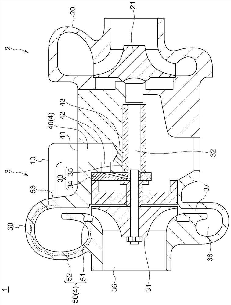
[0076] Such as figure 1 As shown, the turbocharger 1 according to Embodiment 1 of the present disclosure includes a turbine 2 and a centrifugal compressor 3 . The turbine 2 includes a casing 20 and an impeller 21 provided rotatably inside the casing 20 .
[0077] The centrifugal compressor 3 includes: a housing 30 ; an impeller 31 provided rotatably inside the housing 30 ; a rotating shaft 32 connected to the impeller 31 at one end; and a bearing member 33 supporting the rotating shaft 32 in the housing 30 . The bearing member 33 includes: a thrust bearing 34 supporting the rotating shaft 32 in the axial direction of the rotating shaft 32 ; and a journal bearing 35 supporting the rotating shaft 32 in a direction perpendicular to the axial direction of the rotating shaft 32 . The other end of the rotating shaft 32 is connected to the impeller 21 of the turbine 2 . According to this configuration, when the impeller 21 rotates, the rotation is transmitted to the impeller 31 vi...
Embodiment approach 2
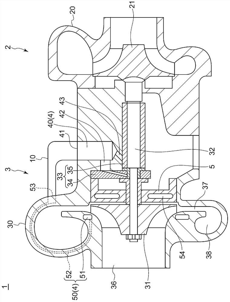
[0093] Next, a turbocharger according to Embodiment 2 will be described. In the turbocharger of the second embodiment, the structure of the oil circulation path 4 is changed from that of the first embodiment. In addition, in Embodiment 2, the same reference numerals are assigned to the same components as those in Embodiment 1, and detailed description thereof will be omitted.
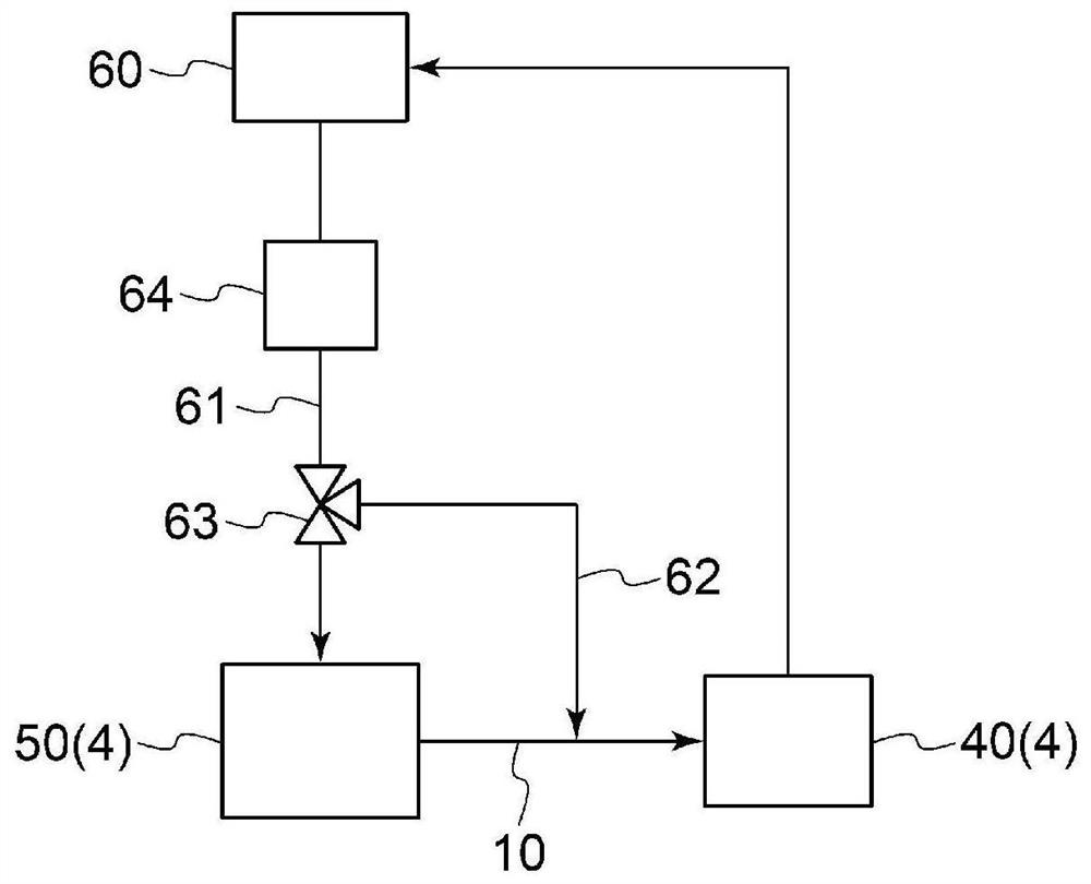
[0094] Such as Figure 4 As shown, in the turbocharger 1 according to Embodiment 2 of the present disclosure, the oil supply source 60 (refer to image 3 ) directly supplies oil as lubricating oil to the lubricating oil passage 40 . The cooling oil passage 50 is configured to include, instead of the communicating portion 52 of the turbocharger 1 according to Embodiment 1, a communicating portion formed so as to surround the periphery of the scroll passage 38 in a direction perpendicular to the axial direction of the scroll passage 38 . Path 55 , one end of the communication path 55 communicates with ...
Embodiment approach 3
[0102] Next, a turbocharger according to Embodiment 3 will be described. In the turbocharger of the third embodiment, the structure of the oil circulation path 4 is changed from that of the first embodiment. In addition, in Embodiment 3, the same reference numerals are assigned to the same components as those in Embodiment 1, and detailed description thereof will be omitted.
[0103] Such as Image 6 As shown, in the turbocharger 1 according to Embodiment 3 of the present disclosure, the oil supply source 60 (refer to image 3 ) directly supplies oil as lubricating oil and cooling oil to the lubricating oil passage 40 and the cooling oil passage 50 , respectively. The lubricating oil path 40 is not branched into two branch paths on the way, but is configured to communicate only with the journal bearing 35 . Lubricating oil path 40 includes an oil supply path 44 communicating with thrust bearing 34 at one end and with annular portion 51 of cooling oil path 50 at the other en...
PUM
 Abstract
Description
Claims
Application Information
 - R&D Engineer
- R&D Manager
- IP Professional
- Industry Leading Data Capabilities
- Powerful AI technology
- Patent DNA Extraction
Browse by: Latest US Patents, China's latest patents, Technical Efficacy Thesaurus, Application Domain, Technology Topic, Popular Technical Reports.
© 2024 PatSnap. All rights reserved.Legal|Privacy policy|Modern Slavery Act Transparency Statement|Sitemap|About US| Contact US: help@patsnap.com