Ureteral stent special for kidney transplantation

A technology for ureter and kidney transplantation, applied in catheters, medical science, guide wires, etc., can solve problems such as ureteral obstruction, increased risk of urinary tract infection, anti-reflux structure damage, etc., to prevent urine reflux, less Calculus remains and effect of improving patency

Pending Publication Date: 2021-03-02
SHANGHAI CHANGZHENG HOSPITAL
View PDF0 Cites 2 Cited by
  • Summary
  • Abstract
  • Description
  • Claims
  • Application Information

AI Technical Summary

Problems solved by technology

[0004] 1) The risk of stenosis and hemorrhage can be reduced after the ureteral stent is placed in the kidney transplant recipient, but there is also a problem, that is, most of the stents currently used in clinical practice are basically through-tubes
In normal humans, there is an anti-reflux mechanism from the ureter to the bladder. When the ureteral stent is placed, the anti-reflux structure will be destroyed. When the patient urinates or holds back the urine, the pressure in the bladder will suddenly increase, causing urine reflux. Backflow to the kidney, causing low back pain in patients, may also increase the risk of early urinary tract infection, and affect the recovery after kidney transplantation;
[0005] 2) After kidney transplantation, the ureteral stent usually needs to be placed for a long period of time, but the existing ureteral stent material will often form small stones on the outer wall of the ureter after being placed in the human body for a long time, and even stones will wrap around the ureter, resulting in The stent is not easy to pull out, or when the stent is pulled out, there are residual small stones that cannot be pulled out together with the stent and remain in the ureter, resulting in secondary ureteral obstruction and urinary tract infection

Method used


Image

  • Ureteral stent special for kidney transplantation
  • Ureteral stent special for kidney transplantation
  • Ureteral stent special for kidney transplantation

Examples


Embodiment Construction

[0019] The following will clearly and completely describe the technical solutions in the embodiments of the present invention with reference to the accompanying drawings in the embodiments of the present invention. Obviously, the described embodiments are only some, not all, embodiments of the present invention. Based on the embodiments of the present invention, all other embodiments obtained by persons of ordinary skill in the art without making creative efforts belong to the protection scope of the present invention.

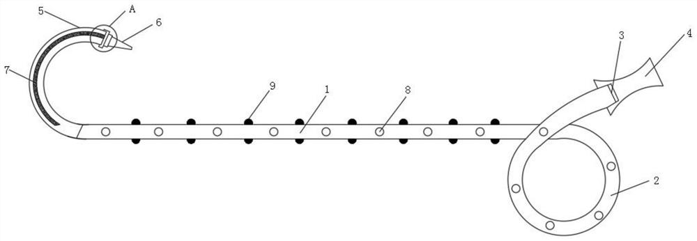
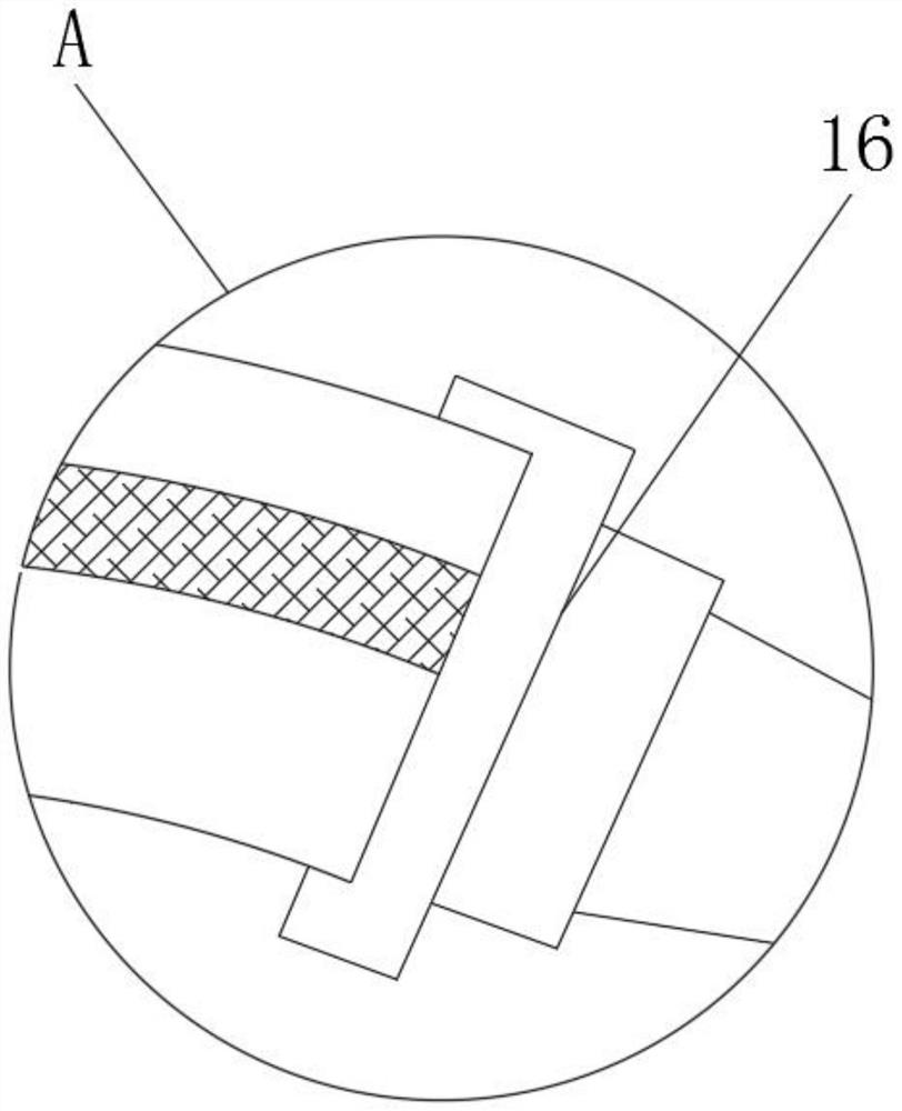
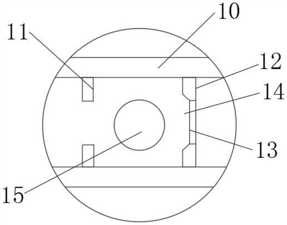
[0020] see Figure 1-4 , a special ureteral stent for kidney transplantation, comprising a stent body 1, a coiled tube 1 2, a nozzle 3, a shut-off tube 4, a coiled tube 2 5, a catheter 6, a curved guide wire 7, a through hole 8, a protrusion 9, and a shut-off tube Wall 10, limit block 11, rubber ring 12, round hole 13, shut-off cavity 14, water blocking ball 15, mounting cap 16 and elastic support body 17; The main structure of the device, one end of the brac...


PUM


Abstract

The invention discloses a ureteral stent special for kidney transplantation. The ureteral stent comprises a stent body, a first curly tube, a tube opening, an intercepting tube, a second curly tube, aguide tube, a bent guide wire, a through hole, a protrusion, an intercepting tube wall, a limiting block, a rubber ring, a round hole, an intercepting cavity, a water blocking ball, a mounting cap and an elastic supporting body. The bent guide wire is made of a plastic material, so that the second coiled tube can be stably fixed in a renal pelvis of a transplanted kidney, the protrusions are allrubber protrusions and can block calculus particles, the stent body is made of a medical silica gel material, the water blocking ball is matched with the round hole, and the stent body is made of a medical silica gel material. The diameter of the water blocking ball is larger than the maximum diameter of the round hole, the phenomenon of urine backflow is prevented conveniently, the smooth layer is arranged in the stent body, a smooth inner surface is provided for the ureteral stent conveniently, smooth passing of fluid is facilitated, and the smoothness of an inner cavity of a tube body of the ureteral stent is improved.

Description

technical field [0001] The invention relates to a ureteral support, in particular to a special ureteral support for kidney transplantation, and belongs to the technical field of medical equipment. Background technique [0002] Ureteral stent is an indispensable medical consumable in urology. It is widely used in the field of urology. It is a commonly used technical tool in the treatment of various benign and malignant urinary system diseases. During the operation of tumor, hydronephrosis, kidney transplantation and other operations. Kidney transplantation refers to a treatment method that transplants a healthy donor kidney to a recipient with kidney disease or loss of kidney function. With the advancement of transplantation technology, the number of kidney transplant operations is also increasing year by year. Patients with end-stage renal disease offer hope. In kidney transplantation, in addition to the necessary anastomosis of renal arteries and veins, ureteral reconstru...

Claims


Application Information

Patent Timeline
Patent Type & Authority Applications(China)
IPC IPC(8): A61M25/14A61M25/09A61M25/04A61B17/22
CPCA61B17/22A61M25/0017A61M25/0043A61M25/005A61M25/0068A61M25/007A61M25/04A61M25/09A61M2025/0059A61M2025/006A61M2025/09133A61M27/008
Inventor 杨璟辉王立明傅尚希鲍海力
Owner SHANGHAI CHANGZHENG HOSPITAL
Why Eureka
Try Eureka