
Flanging and internal spinning composite forming method and device for flange

A compound forming and internal spinning technology, applied in the field of forging, can solve the problems of flange neck deformation, restricting production efficiency, affecting yield, etc., to prevent the movement of forgings, save equipment investment and energy consumption, and easy demoulding Effect

Active Publication Date: 2021-03-02
GUIZHOU AEROSPACE XINLI CASTINGSAND FORGINGS
View PDF23 Cites 3 Cited by
  • Summary
  • Abstract
  • Description
  • Claims
  • Application Information

AI Technical Summary

Problems solved by technology

[0005] However, both of the above two technologies have a limitation: the frictional resistance is very large during the stretching process of the slab, and after the stretching is completed, the billet is completely wrapped on the punch, making demoulding difficult
This problem has been restricting the improvement of production efficiency
Especially for thin-walled high-neck flanges, because the neck wall thickness is thin and the size is long, even if the covering force of the material on the punch is too large during demoulding, the flange neck will be deformed and the yield will be affected.

Method used


Image

  • Flanging and internal spinning composite forming method and device for flange

Examples


Embodiment Construction

[0030] The technical solution of the present invention is further described below, but the scope of protection is not limited to the description.

[0031] The present invention provides a flange flanging internal spinning composite molding method, comprising the following steps:

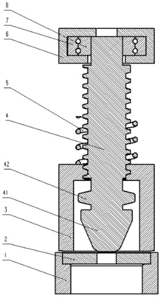
[0032] ① Firstly, the slab 2 is made into a round blank, and the guide hole is processed in the center of the slab 2;

[0033] ②Heat the slab 2 and place it on the lower flanging mold 1, and place the blank holder 3 on the slab 2, start the hydraulic press, the punch screw 4 and the blank holder 3 are threaded, and under the action of the thread The punch screw 4 rotates and moves downward until it touches the slab 2, and the punch screw 4 squeezes the blank holder 3 under the action of the spring 5 and the thread, the punch screw 4, the blank holder 3, and the lower flange 1 jointly compress the slab 2;

[0034] ③Punch screw 4 continues to rotate and move downward, the end punch 41 passes through ...


PUM


Abstract

The invention provides a flanging and internal spinning composite forming method for a flange. The method comprises the steps that firstly, a guide hole is formed in the center of a circular plate blank, the circular plate blank is heated and put on a lower flanging die, a hydraulic machine is started, a punch screw is made to move downwards under the action of the hydraulic machine, a blank holder is made to press the plate blank, the punch screw is made to rotate downwards under the threaded fit with the blank holder, an end punch is used for spinning to expand the guide hole, and a materialis overturned downwards; further, two punches at the neck part of the punch screw are used for spinning the neck part of the flange in a progressive manner, and thus the neck part of the flange is further thinned and extends downwards; and until the size is in place, the hydraulic machine returns, and the punch screw is reset under the action of a spring. The punches rotate to move downwards, small-area rapid progressive rotary extrusion forming is adopted, the coating force of the material on the punches is reduced, demolding is easy, fillets between the neck and the end of the flange are reduced, the impact force needed by forming is reduced, and the size and the weight of equipment are reduced.

Description

technical field [0001] The invention belongs to the technical field of forging, and relates to a stretch flanging internal spinning compound forming method of a thin-walled high-necked flange. Background technique [0002] Flanges are commonly used mechanical connection parts. For the manufacture of flanges, the commonly used methods are: forming by die forging, and then performing a large number of mechanical processing; Processing; sometimes also includes the process of welding. These methods have many molding processes, low material utilization rate, and a large amount of mechanical processing cuts off the metal fibers, reducing the service life and comprehensive performance of the product. [0003] The Chinese patent whose publication number is CN109648255A discloses a composite forming process of plate forging and rolling for large flanges. For flange workpieces that meet the size, after stress relief treatment, the flange workpieces can be turned, chamfered, and insp...

Claims


Application Information

Patent Timeline
Patent Type & Authority Applications(China)
IPC IPC(8): B21D22/14B21D43/00B21D19/08B21D35/00B21D37/10B21D37/16
CPCB21D22/14B21D43/003B21D19/08B21D35/002B21D37/10B21D37/16
Inventor 赵晓光张明桥冉雄波梁启超傅名娇付朝政李卓林
Owner GUIZHOU AEROSPACE XINLI CASTINGSAND FORGINGS
Learn More