Large-rotary continuous feeding and waste discharging system

A material feeding and waste technology, applied in metal processing and other directions, can solve the problems of large floor space, increased operating costs of paper cutters, and increased costs, and achieve the effects of improving production efficiency, reducing idle running time, and realizing automation.

Pending Publication Date: 2021-03-02
柳州市卓信自动化设备有限公司
View PDF0 Cites 0 Cited by
  • Summary
  • Abstract
  • Description
  • Claims
  • Application Information

AI Technical Summary

Problems solved by technology

However, the first paper cutter was in an idle state from the end of the head cutting to the tail cutting, which led to an increase in the operating cost of the paper cutter, and the use of the dual-machine working mode not only occupies a larger area , each machine also needs to be equipped with a separate operator to operate, resulting in increased costs

Method used


Image

  • Large-rotary continuous feeding and waste discharging system
  • Large-rotary continuous feeding and waste discharging system
  • Large-rotary continuous feeding and waste discharging system

Examples


Embodiment 1

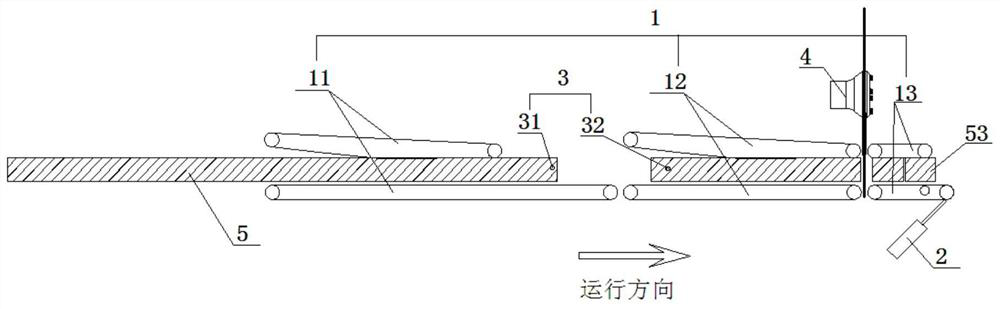
[0054] figure 1 It shows an implementation form of the present invention, a large-circle continuous feeding and waste discharge system, including:

[0055] The feeding and conveying system 1 includes a first clamping and conveying unit 11, a second clamping and conveying unit 12 and a third clamping and conveying unit 13 arranged in sequence along the feeding direction, and the clamping and conveying unit is composed of conveyor belts arranged up and down oppositely , the feeding conveying channel is formed between the upper and lower conveyor belts, and the horizontal linear feeding channel composed of the first feeding conveying channel, the second feeding conveying channel and the third feeding conveying channel corresponding to the three clamping conveying units respectively The lower conveyor belt of the third clamping and conveying unit allows one end to swing up and down, and a telescopic mechanism 2 is arranged below the third clamping and conveying unit to support the...

Embodiment 2

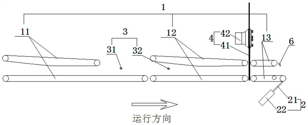
[0064] figure 2 It shows an implementation form of the present invention, a large-circle continuous feeding and waste discharge system, including:

[0065] The feeding and conveying system 1 includes a first clamping and conveying unit 11, a second clamping and conveying unit 12 and a third clamping and conveying unit 13 arranged in sequence along the feeding direction, and the clamping and conveying unit is composed of conveyor belts arranged up and down oppositely , the feeding conveying channel is formed between the upper and lower conveyor belts, and the horizontal linear feeding channel composed of the first feeding conveying channel, the second feeding conveying channel and the third feeding conveying channel corresponding to the three clamping conveying units respectively The lower conveyor belt of the third clamping and conveying unit allows one end to swing up and down, and a telescopic mechanism 2 is arranged below the third clamping and conveying unit to support th...


PUM


Abstract

The invention discloses a large-rotary continuous feeding and waste discharging system. The large-rotary continuous feeding and waste discharging system comprises a feeding conveying system, detectionswitches, a rotary cutter set and a control system, wherein the detection switches comprise a first detection switch and a second detection switch so as to respectively detect the positions of the paper head and the paper tail; the rotary cutter set is arranged between a second clamping and conveying unit and a third clamping and conveying unit and used for cutting long-strip paper materials; andthe control system controls the first clamping and conveying unit to operate in an accelerated mode to shorten the distance between the long-strip paper materials at the two ends according to detection signals of the detection switches, then the control system accelerates the cutting frequency of the rotary cutter set to rapidly cut the paper tails and the paper heads of the long-strip paper materials, and finally, a telescopic mechanism is controlled to stretch out and draw back to discharge the paper tails and paper heads. Compared with a traditional paper cutting machine, the large-rotarycontinuous feeding and waste discharging system has the advantages that the head, the tail and finished products of paper are continuously cut off, and the production efficiency is greatly improved.

Description

technical field [0001] The invention relates to the technical field of paper cutting. More specifically, the present invention relates to a continuous feed and waste discharge system with large swirls. Background technique [0002] The large rotary paper cutter is an important machine in the high-speed automatic production line of toilet paper and kitchen paper, which can greatly improve the automation degree and production efficiency of the production line. [0003] At present, the feeding method of the large rotary paper cutter is a single paper material feeding independently. In order to ensure the smoothness of the edges of the two ends of the finished product, it is necessary to cut off the head and tail of the paper material. Due to the lack of two continuous strips of paper material The position detection feedback of the paper head and paper tail, the control system can not know its exact position, must wait for the previous paper material to be cut in the process of...

Claims


Application Information

Patent Timeline
IPC IPC(8): B26D1/15B26D5/00B26D7/06B26D7/27B26D7/18
CPCB26D1/151B26D5/00B26D7/0633B26D7/18B26D7/1854B26D7/27B26D2005/002
Inventor 孟明雄刘天托
Owner 柳州市卓信自动化设备有限公司
Why Eureka
Try Eureka