Concrete continuous output stirring device for road construction

A road construction and mixing device technology, which is applied in the direction of cement mixing device, clay preparation device, unloading device, etc., can solve the problems that the continuous mixing of concrete can not be realized and the output function can not be realized.

Active Publication Date: 2021-03-02
武汉兴合创建筑材料有限公司
View PDF8 Cites 1 Cited by
  • Summary
  • Abstract
  • Description
  • Claims
  • Application Information

AI Technical Summary

Problems solved by technology

[0004] Chinese patent (notification number: CN208899877U) discloses a new type of concrete output device, the indicator table is embedded and installed on the body, the upper end surface of the support leg is welded to the upper end surface of the body, and the fixing screw is embedded and installed on the body And threaded connection, the liquid suction pump is arranged inside the shell, the sliding plate is embedded and installed on the moving frame and has clearance fit, the limit ball is located above the spring, the pinion is meshed with the fixed pin, and the The track is set inside the shell, the gear is embedded...

Method used


Image

  • Concrete continuous output stirring device for road construction
  • Concrete continuous output stirring device for road construction
  • Concrete continuous output stirring device for road construction

Examples


Embodiment 1

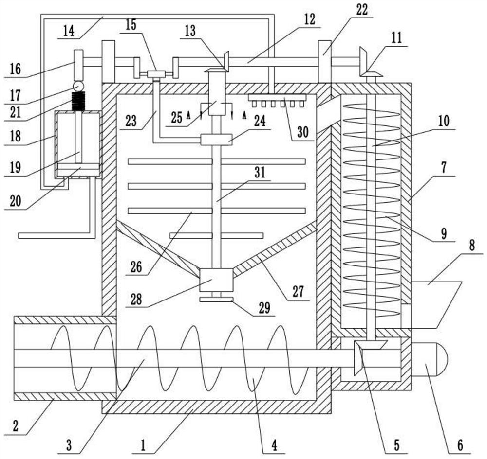
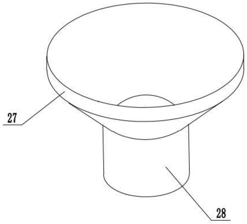
[0028] refer to Figure 1~3 , in an embodiment of the present invention, a concrete continuous output mixing device for road construction, comprising a mixing box 1, supporting frames 22 are installed on both sides of the upper end of the mixing box 1, and a drive shaft 12 is arranged to rotate between the supporting frames 22, and the A retaining ring 27 is installed inside the mixing box 1, thereby ensuring that the concrete material can effectively enter the interior of the feeding pipe 28, the bottom of the retaining ring 27 is equipped with a feeding pipe 28, and the right side of the mixing box 1 is equipped with a feeding cylinder 7, A feeding hopper 8 is installed at the bottom of the right side of the feeding cylinder 7, and the feeding hopper 8 communicates with the bottom of the feeding cylinder 7 to ensure that the external solid material is introduced into the feeding material 8, thereby flowing into the inside of the feeding cylinder 7, The feeding shaft 10 is in...

Embodiment 2

[0030] In another embodiment of the present invention, the difference between this embodiment and the above-mentioned embodiment is that, wherein, a feed screw 9 is installed on the outside of the feed shaft 10, which is used to realize that the concrete solid material passes through the feed cylinder The function of 7 is the introduction function to the inside of the mixing box 1.

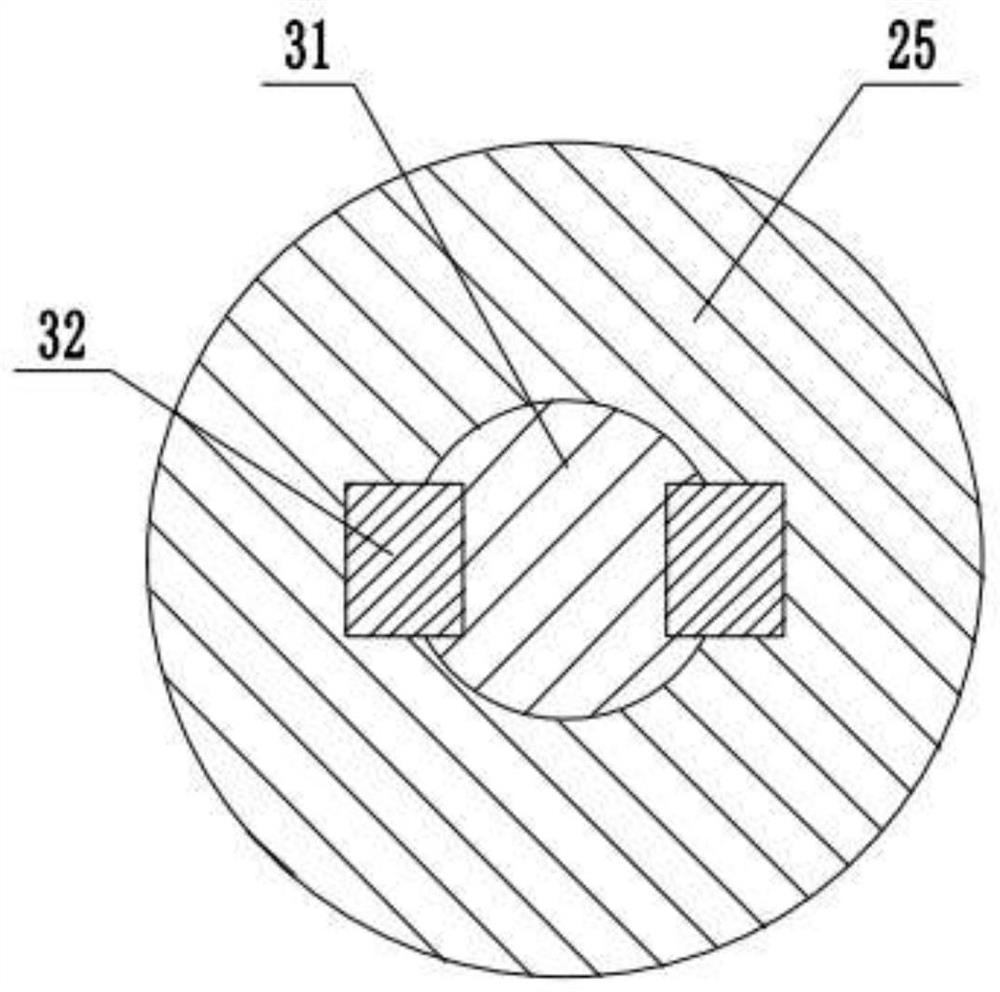
[0031]The present invention, when working, first starts the driving motor 6, and the solid raw materials and liquid raw materials of the concrete are transported through the liquid introduction box 18 and the feeding cylinder 7, and the driving shaft 10 rotates at the same time, and the rotation is made under the action of the third gear set 13 The barrel 25 rotates, and the stirring shaft 31 drives the stirring blade 26 to rotate synchronously. On the other hand, with the cooperation of the L-shaped frame 23 and the crank mechanism 15, the stirring shaft 31 moves up and down while rotating, so tha...


PUM


Abstract

The invention relates to the technical field of concrete output devices, and discloses a continuous concrete output stirring device for road construction. The continuous concrete output stirring device comprises a stirring box, wherein a rotating cylinder is rotatably mounted in the middle of the upper end of the stirring box, a stirring shaft is connected into the rotating cylinder through a flatkey, and a conveying plate matched with a conveying pipe is mounted at the bottom of the stirring shaft; the middle part of the upper end of the stirring shaft is provided with a bearing seat, the left side of the bearing seat is provided with an L-shaped frame, an output barrel is installed at the left side of the lower end of the stirring box, an output shaft is installed in the middle of the output barrel, a plurality of output screws are installed in the middle of the output shaft, a first gear set is installed between the right end of the output shaft and the bottom of a feeding shaft, and a driving shaft is installed at the top end of the feeding shaft through a second gear set; and the middle of the driving shaft is mounted at the top end of the rotating cylinder through a third gear set, and a crank mechanism is mounted in the middle of the left end of the driving shaft, so that liquid and solid in concrete raw materials are fully mixed and stirred, stirred concrete is effectively conveyed, the blockage phenomenon is avoided, and continuous output of the concrete is ensured.

Description

technical field [0001] The invention relates to the technical field of concrete output devices, in particular to a concrete continuous output mixing device for road construction. Background technique [0002] Concrete is a general term for engineering composite materials in which aggregates are cemented into a whole by cementitious materials. Generally speaking, the term concrete refers to the cement concrete obtained by using cement as the cementitious material, sand and stone as the aggregate; mixed with water (may contain admixtures and admixtures) in a certain proportion, and stirred. Concrete, which is widely used in civil engineering. [0003] Inorganic cementitious materials such as cement, lime, and gypsum are mixed with water to make the concrete mixture plastic; and then through chemical and physical and chemical actions, it coagulates and hardens to produce strength. Generally speaking, drinking water can meet the requirements of concrete mixing water. Excess a...

Claims


Application Information

Patent Timeline
IPC IPC(8): B28C5/16B28C5/08B28C7/10B28C7/16
CPCB28C5/16B28C5/0806B28C5/0831B28C7/10B28C7/167
Inventor 张丽于志光
Owner 武汉兴合创建筑材料有限公司
Why Eureka
Try Eureka