Polarizer and display panel

A technology for display panels and polarizers, applied in optics, optical elements, polarizing elements, etc., can solve the problems of poor display effect and easy breakage of conductive adhesive, so as to prevent the quality and display effect from being affected, and prevent excessive conductive adhesive. , the effect of reducing the height

Inactive Publication Date: 2021-03-02
WUHAN CHINA STAR OPTOELECTRONICS SEMICON DISPLAY TECH CO LTD
View PDF2 Cites 3 Cited by
  • Summary
  • Abstract
  • Description
  • Claims
  • Application Information

AI Technical Summary

Problems solved by technology

[0005] In order to improve the above problems, the embodiment of the present invention provides a display panel and a polarizer, which

Method used


Image

  • Polarizer and display panel
  • Polarizer and display panel

Examples


Example Embodiment

[0031]The technical solutions in the embodiments of the present invention will be clearly and completely described below in conjunction with the accompanying drawings in the embodiments of the present invention. Obviously, the described embodiments are only a part of the embodiments of the present invention, rather than all the embodiments. Based on the embodiments of the present invention, all other embodiments obtained by those skilled in the art without creative work shall fall within the protection scope of the present invention.

[0032]In the description of the present invention, it should be understood that the terms "center", "longitudinal", "transverse", "length", "width", "thickness", "upper", "lower", "front", " The orientation or positional relationship indicated by “rear”, “left”, “right”, “vertical”, “horizontal”, “top”, “bottom”, “inner”, and “outer” are based on the orientation shown in the drawings The or positional relationship is only for the convenience of describin...


PUM


Abstract

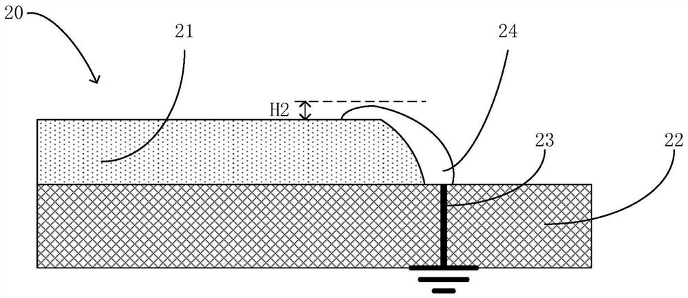
The invention discloses a polaroid and a display panel. The shape of at least one side edge of the polaroid in the cross section is set to be an unfilled corner, and the unfilled corner is arranged onthe side edge of the polaroid, so that stress generated by an original right angle is reduced, conductive adhesive arranged on the edge of the polaroid is prevented from being broken after adhesive climbing, and problems that static electricity cannot be led out, and the effect of the display panel is poor are prevented.

Description

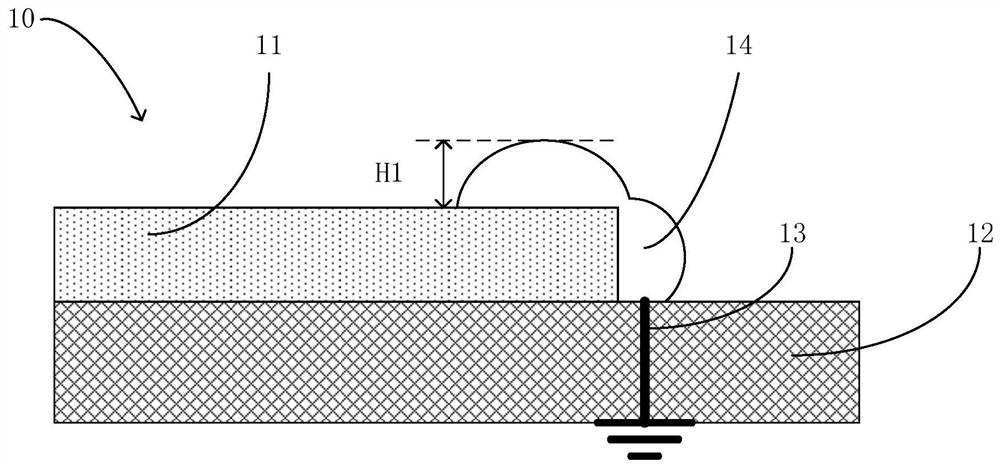
technical field [0001] The invention relates to the field of display technology, in particular to a polarizer and a display panel. Background technique [0002] Organic light-emitting diode (Organic Light-Emitting Diode, OLED), also known as organic electrical laser display, organic light-emitting semiconductor, was discovered in the laboratory by scientist Ching W.Tang in 1979. OLED display technology has the advantages of self-illumination, wide viewing angle, almost infinitely high contrast, low power consumption, and extremely high response speed. [0003] Such as figure 1 As shown, an existing OLED display panel 10 includes: a glass cover (not shown), a polarizer 11 , an OLED layer 12 , a backplane (not shown), and the like. The glass cover is affected by ambient light, so a polarizer is needed to eliminate the ambient light, so that the chromaticity and brightness displayed by the OLED display panel 10 are more uniform, but the surface of the polarizer 11 will have s...

Claims


Application Information

Patent Timeline
IPC IPC(8): G02B5/30H01L27/32H01L51/52
CPCG02B5/3058H10K59/12H10K50/86
Inventor 陈毅成文红
Owner WUHAN CHINA STAR OPTOELECTRONICS SEMICON DISPLAY TECH CO LTD
Why Eureka
Try Eureka