Laser fiber coupling debugging device and method

An optical fiber coupling and testing device technology, which is applied to the coupling of optical waveguides, measuring devices, optical instrument testing, etc. strong effect

Pending Publication Date: 2021-03-02
XI'AN INST OF OPTICS & FINE MECHANICS - CHINESE ACAD OF SCI
View PDF0 Cites 2 Cited by
  • Summary
  • Abstract
  • Description
  • Claims
  • Application Information

AI Technical Summary

Problems solved by technology

[0007] The purpose of the present invention is to provide a device and method for optical fiber coupling debuggin

Method used


Image

  • Laser fiber coupling debugging device and method
  • Laser fiber coupling debugging device and method
  • Laser fiber coupling debugging device and method

Examples


Example Embodiment

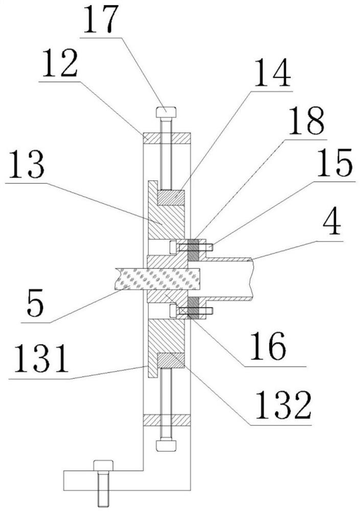
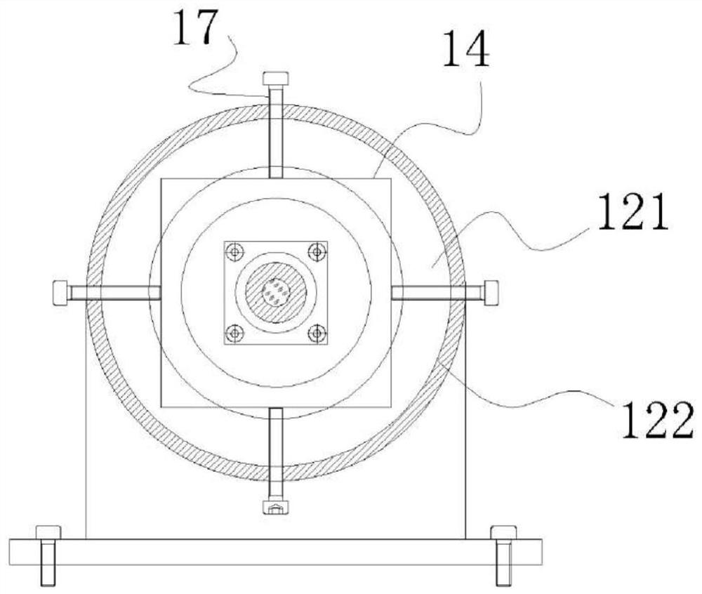
[0052] The core of the present invention is to provide a device and method capable of co-modulating the coaxiality and polarization state of the optical axis between the laser fiber 5 and the laser emitting or receiving mirror group.

[0053] In order to make the objectives, technical solutions and advantages of the present invention more clearly understood, the present invention will be further described in detail below in conjunction with the specific embodiments and with reference to the accompanying drawings.
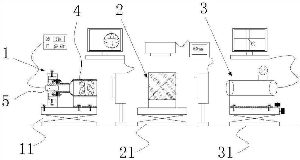
[0054] The laser fiber coupling debugging device includes a test device 3 for testing the coaxiality of the mirror group 4 to be adjusted and the laser fiber 5, a detection device 2 for detecting the polarization state of the mirror group 4 to be adjusted and the laser fiber 5, and a test device 2 according to the test and the detection result to adjust and fix the adjustment tool 1 of the mirror group 4 to be adjusted and the laser fiber 5; the adjustment tool 1 is ...


PUM


Abstract

The invention provides an optical fiber coupling debugging device and method, and mainly solves the problem that the coaxiality and the polarization state cannot be jointly debugged in the prior art.According to the invention, a testing device used for testing the coaxiality of a to-be-adjusted lens group and a laser fiber, a detection device used for detecting the polarization states of the to-be-adjusted lens group and the laser fiber, and an adjustment tool used for adjusting and fixing the to-be-adjusted lens group and the laser fiber according to testing and detection results are used for the detection and joint adjustment of the coaxiality and the polarization states. The optical fiber coupling debugging device and method are simple in adjustment, convenient to operate and high in efficiency.

Description

technical field [0001] The invention relates to the field of optical instrument assembly and adjustment, in particular to a method for adjusting coaxiality and polarization state in the coupling process of laser communication optical fibers. Background technique [0002] In the field of laser communication, optical fibers are mainly used to transmit laser signals. The laser signal is transmitted to the laser emitting mirror group through the laser generator through the optical fiber, and after a series of processing in the optical device, it is output from the laser receiving mirror group. [0003] The connector flange of the laser fiber is connected with the flanges of the laser emitting and receiving mirror groups by screws. This connection method cannot directly ensure that the optical axis of the optical fiber coincides with the optical axis of the corresponding mirror group, nor can it strictly guarantee its polarization direction. [0004] 201922101566.4 provides a to...

Claims


Application Information

Patent Timeline
IPC IPC(8): G02B6/42G01M11/02G01M11/00
CPCG01M11/0257G01M11/31G01M11/3181G02B6/4222G02B6/4226G02B6/4296
Inventor 曹明强侯晓华雷昱刘勇李小燕张鸽韩娟
Owner XI'AN INST OF OPTICS & FINE MECHANICS - CHINESE ACAD OF SCI
Why Eureka
Try Eureka