Light source module for DLP micro projector ray machine, ray machine and DLP projector

A light source module and micro-projection technology, applied in the field of DLP projectors and optical machines, can solve the problems of low energy utilization of light sources, affecting the volume of projectors, cost, uncontrollable tolerances, etc., to improve projection uniformity and projection quality , Improve energy utilization, reduce the effect of positioning error

Active Publication Date: 2021-03-02
SHENZHEN ANHUA OPTOELECTRONICS TECH
View PDF7 Cites 0 Cited by
  • Summary
  • Abstract
  • Description
  • Claims
  • Application Information

AI Technical Summary

Problems solved by technology

It can be seen that the lighting system needs to go through the longest optical transmission path to reach the target projection plane. The lighting system is a crucial part of the projector system, which determines the energy utilization rate, projection uniformity, and projection quality of the entire projection system; In addition, the lighting system also affects the volume, cost and other aspects of the performance of the projector. For example, when the energy utilization rate of the light source is low and cannot meet the energy demand, it is necessary to configure a larger volume of light source, which will lead to complete machine matching. The size of the parts increases accordingly
[0004] The applicant's research shows that the installation accuracy of the three-color LED will directly affect the transmission direction of the light source, thereby further affecting the utilization rate of the light source, that is, the energy utilization rate of the light source
In the prior art, the PCB board equipped with three-color LEDs is often directly fixed on the main housing of the projector or the housing of the collimation system by means of screws, studs or gluing. However, the PCB board and the main housing of the projector There is a large tolerance between the PCB board and the housing of the collimation system, and the existing tolerance is uncontrollable. Therefore, this fixing method will bring a large positioning error, which will cause the LED light-emitting chip There is a large positioning error with the collimation system. After a long transmission path, the positioning error will be amplified, which will cause serious attenuation of light energy, and then seriously affect the projection uniformity on the projection plane. and projection quality

Method used


Image

  • Light source module for DLP micro projector ray machine, ray machine and DLP projector
  • Light source module for DLP micro projector ray machine, ray machine and DLP projector
  • Light source module for DLP micro projector ray machine, ray machine and DLP projector

Examples


Embodiment Construction

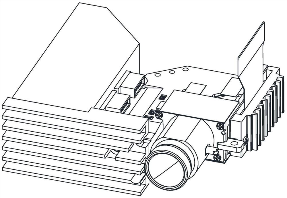
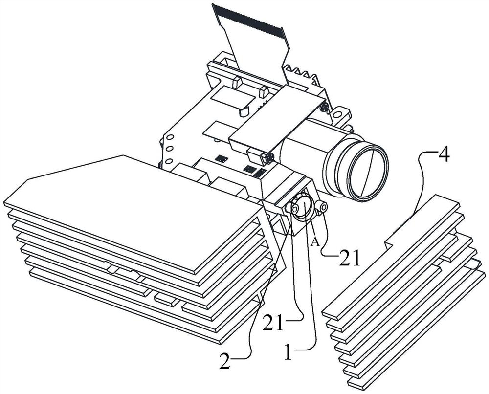
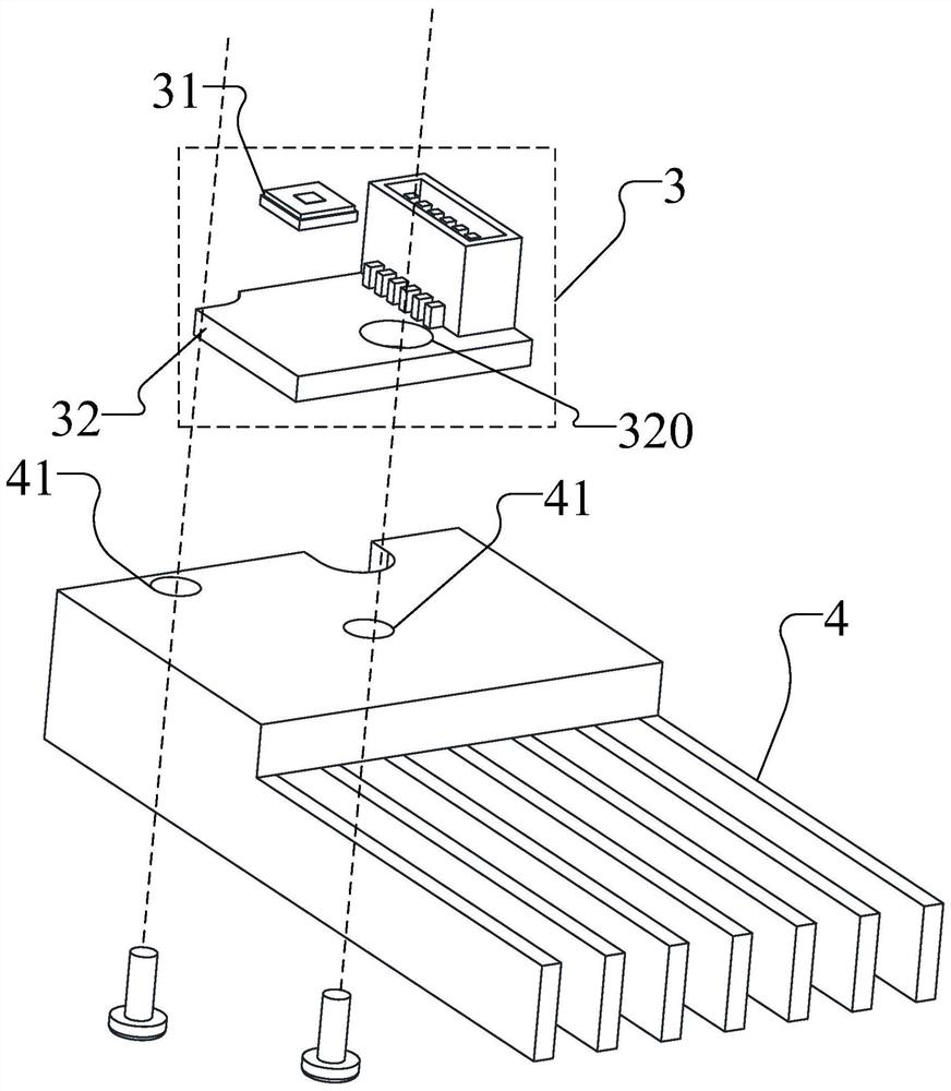
[0040] In a DLP projector, in order to improve the energy utilization rate of the light source, improve the projection uniformity and the projection quality, this embodiment discloses a light source module for a DLP micro-projector optical machine and an optical machine with it, and a DLP projection projector. instrument, DLP projector includes light machine, please refer to figure 1 , figure 2 with image 3 ,in, figure 1 It is a schematic structural diagram of a DLP projector optical machine disclosed in this embodiment, figure 2 It is a schematic diagram of the state of a DLP projector disclosed in this embodiment after the optical machine separates a light source module, image 3 It is a schematic diagram of an explosion of a light source module disclosed in this embodiment. In a specific embodiment, the optical machine includes a collimator lens 1, a collimator lens mount 2 and a light source module without reference numerals, wherein the light source module It inclu...


PUM


Abstract

The invention discloses a light source module for a DLP micro projector ray machine, the ray machine with the same, and a DLP projector. An LED light source device comprises an LED light-emitting chipand a PCB, the LED light-emitting chip is arranged on the PCB, the light-emitting surface of the LED light-emitting chip is back to the PCB, an LED drive circuit is arranged on the PCB, the LED light-emitting chip is electrically connected with the LED drive circuit, and the LED driving circuit is used for driving the LED light-emitting chip to emit light; a radiator is made of a rigid material and is provided with a positioning part, so that the radiator can be positioned on the collimating lens mounting seat; the PCB is directly fixed to the radiator in a gluing mode. and the PCB is installed on a collimating lens installation base through the radiator, so that the light-emitting face of the LED light-emitting chip faces the collimating lens and is located on the optical axis of the collimating lens. The energy utilization rate of the light source is improved, so that the projection uniformity and the projection quality of the ray machine can be integrally improved.

Description

technical field [0001] The invention relates to the technical field of DLP projection, in particular to a light source module used for a DLP micro-projector optical machine, an optical machine having the same, and a DLP projector. Background technique [0002] Micro-projection technology is a new type of modern projection display technology. With its miniaturization and portability, it gradually penetrates into people's daily life, and has gradually become an important development trend of projection display. The digital light processing (Digital Light Processing, DLP) projection display method has the characteristics of high brightness, high contrast, and high resolution. It is combined with a new LED light source to realize a miniaturized portable micro-projection, which meets people's desire for portable and free projection display. demand. [0003] DLP projectors often use three-color (R, G, B) diodes (LEDs) as light sources, where the R, G, and B diodes can be driven t...

Claims


Application Information

Patent Timeline
Patent Type & Authority Applications(China)
IPC IPC(8): G03B21/14G03B21/16G03B21/20
CPCG03B21/142G03B21/16G03B21/2033G03B21/206
Inventor 朱青孙峰王中俭
Owner SHENZHEN ANHUA OPTOELECTRONICS TECH
Why Eureka
Try Eureka