

Image reconstruction method and system for distorted color direct component marking
A component marking and image reconstruction technology, applied in image analysis, graphics and image conversion, image data processing, etc., can solve problems such as distortion, uneven color of marking modules, uneven marking depth and texture size, etc., and achieve fast and accurate positioning , Improve readability, improve the effect of module color changes
- Summary
- Abstract
- Description
- Claims
- Application Information
AI Technical Summary
Problems solved by technology
Method used
Image

Examples
Embodiment 1
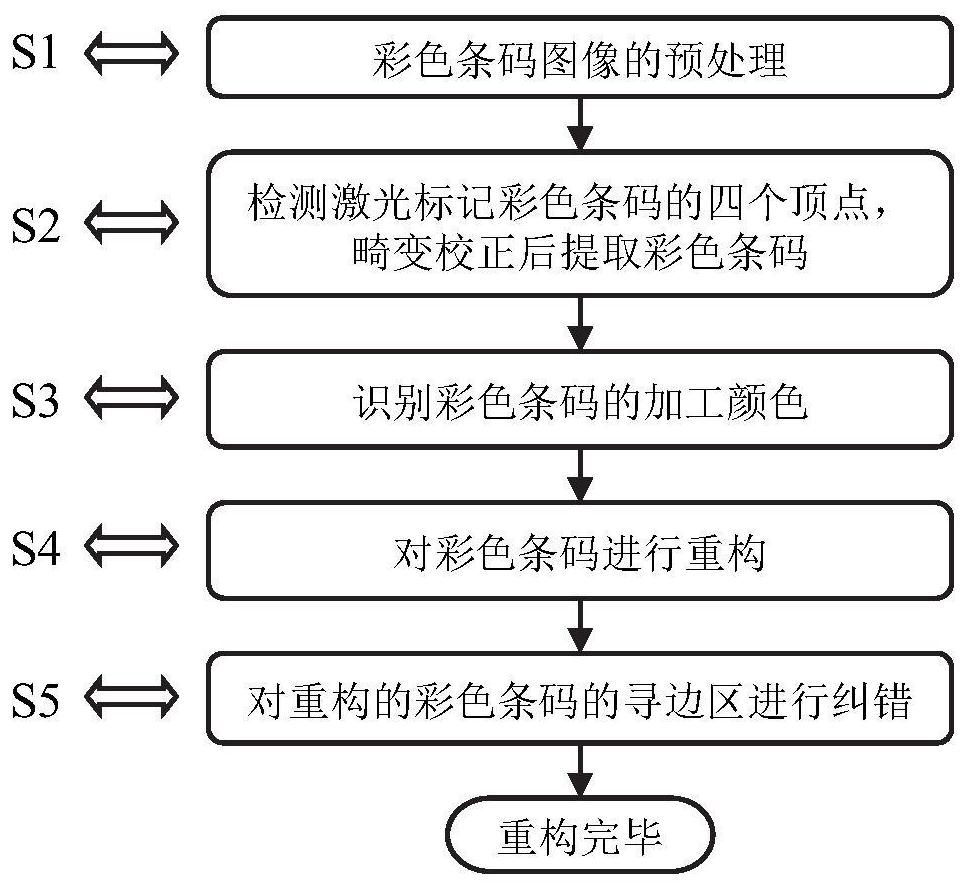
[0062] This embodiment discloses an image reconstruction method for distorted color direct component marking, figure 1 It is a flowchart of image reconstruction technology for distorted color direct part marking according to an embodiment of the present disclosure.
[0063] The specific content is as follows:
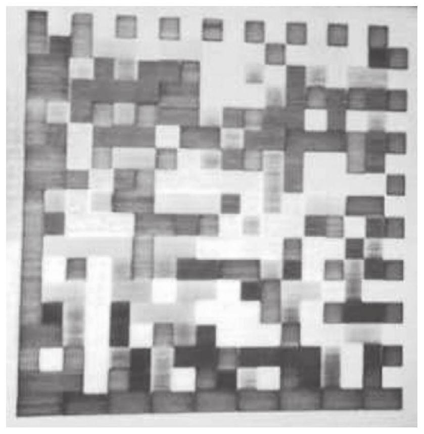
[0064] S1: if figure 2 As shown, load the collected laser-marked color Data Matrix barcode image, and perform the following preprocessing steps in sequence: the apex of the L solid edge of the barcode is located in the lower left corner of the image, use the weighted average method to grayscale the image, and use the Sauvola algorithm Binarize the grayscale image, use the Canny operator to detect the boundary of the binarized image, and use the Hough transform to detect the straight line in the image;
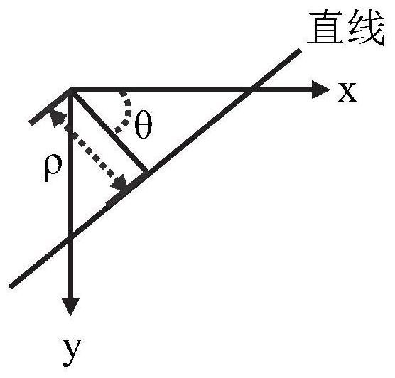
[0065] S2: Detect the four vertices of the color Data Matrix barcode, the steps are as follows:
[0066] Such as image 3 As shown, ρ is the vertical vector from th...
Embodiment 2
[0086] The purpose of this embodiment is to provide a computing device, including a memory, a processor, and a computer program stored in the memory and operable on the processor. step.
Embodiment 3
[0088] The purpose of this embodiment is to provide a computer-readable storage medium.
[0089] A computer-readable storage medium, on which a computer program is stored, and when the program is executed by a processor, the specific steps in the first embodiment above are executed.
PUM
 Abstract
Description
Claims
Application Information